Descriptions and Functions
FRONT
4 5 6 7
Progressive Scan
EJECT | PLAY | STOP | PREV | NEXT |
|
| MIC 1 | MIC 2 | MIC VOL | ECHO | |
|
|
|
| ||
POWER
DVX-680K
V I D E O
CDG
1 | 3 | 2 | 8 | 9 | 10 |
1 | 2 | 3 | 8 | 9 | 10 |
FL | FR | SUB | Y | Cb | Cr | VIDEO |
|
SL | SR | CENTER | L | R | COAXIAL | OPTICAL |
|
| Serial No. |
|
| Manufactured under License from Dolby Laboratories |
|
| DOLBY PRO LOGIC and the |
|
| trademarks of Dolby Laboratories. Confidential |
| VGA | |
|
| trademarks of Dolby Laboratories. Confidential |
SCART OUT |
| Manufactured under License from Dolby Laboratories |
| DOLBY PRO LOGIC and the | |
![]() CAUTION
CAUTION ![]()
RISK OF ELECTRIC SHOCK
DO NOT OPEN
AC IN
4 | 5 | 6 | 7 |
REAR
FRONT
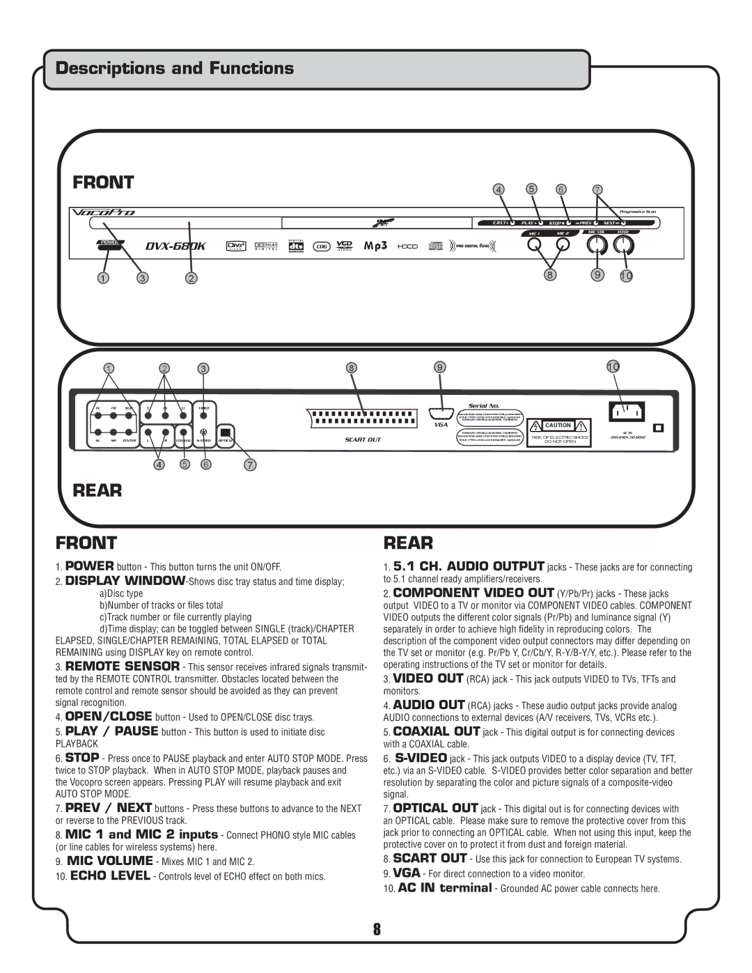
1.POWER button - This button turns the unit ON/OFF.
2.DISPLAY
b)Number of tracks or files total c)Track number or file currently playing
d)Time display; can be toggled between SINGLE (track)/CHAPTER ELAPSED, SINGLE/CHAPTER REMAINING, TOTAL ELAPSED or TOTAL REMAINING using DISPLAY key on remote control.
3.REMOTE SENSOR - This sensor receives infrared signals transmit- ted by the REMOTE CONTROL transmitter. Obstacles located between the remote control and remote sensor should be avoided as they can prevent signal recognition.
4.OPEN/CLOSE button - Used to OPEN/CLOSE disc trays.
5.PLAY / PAUSE button - This button is used to initiate disc
PLAYBACK
6.STOP - Press once to PAUSE playback and enter AUTO STOP MODE. Press twice to STOP playback. When in AUTO STOP MODE, playback pauses and
the Vocopro screen appears. Pressing PLAY will resume playback and exit
AUTO STOP MODE.
7.PREV / NEXT buttons - Press these buttons to advance to the NEXT or reverse to the PREVIOUS track.
8.MIC 1 and MIC 2 inputs - Connect PHONO style MIC cables (or line cables for wireless systems) here.
9.MIC VOLUME - Mixes MIC 1 and MIC 2.
10.ECHO LEVEL - Controls level of ECHO effect on both mics.
REAR
1.5.1 CH. AUDIO OUTPUT jacks - These jacks are for connecting to 5.1 channel ready amplifiers/receivers.
2.COMPONENT VIDEO OUT (Y/Pb/Pr) jacks - These jacks output VIDEO to a TV or monitor via COMPONENT VIDEO cables. COMPONENT VIDEO outputs the different color signals (Pr/Pb) and luminance signal (Y) separately in order to achieve high fidelity in reproducing colors. The description of the component video output connectors may differ depending on the TV set or monitor (e.g. Pr/Pb Y, Cr/Cb/Y,
3.VIDEO OUT (RCA) jack - This jack outputs VIDEO to TVs, TFTs and monitors.
4.AUDIO OUT (RCA) jacks - These audio output jacks provide analog AUDIO connections to external devices (A/V receivers, TVs, VCRs etc.).
5.COAXIAL OUT jack - This digital output is for connecting devices with a COAXIAL cable.
6.
7.OPTICAL OUT jack - This digital out is for connecting devices with an OPTICAL cable. Please make sure to remove the protective cover from this jack prior to connecting an OPTICAL cable. When not using this input, keep the protective cover on to protect it from dust and foreign material.
8.SCART OUT - Use this jack for connection to European TV systems.
9.VGA - For direct connection to a video monitor.
10.AC IN terminal - Grounded AC power cable connects here.
8