GETTING STARTED
WALL MOUNTING
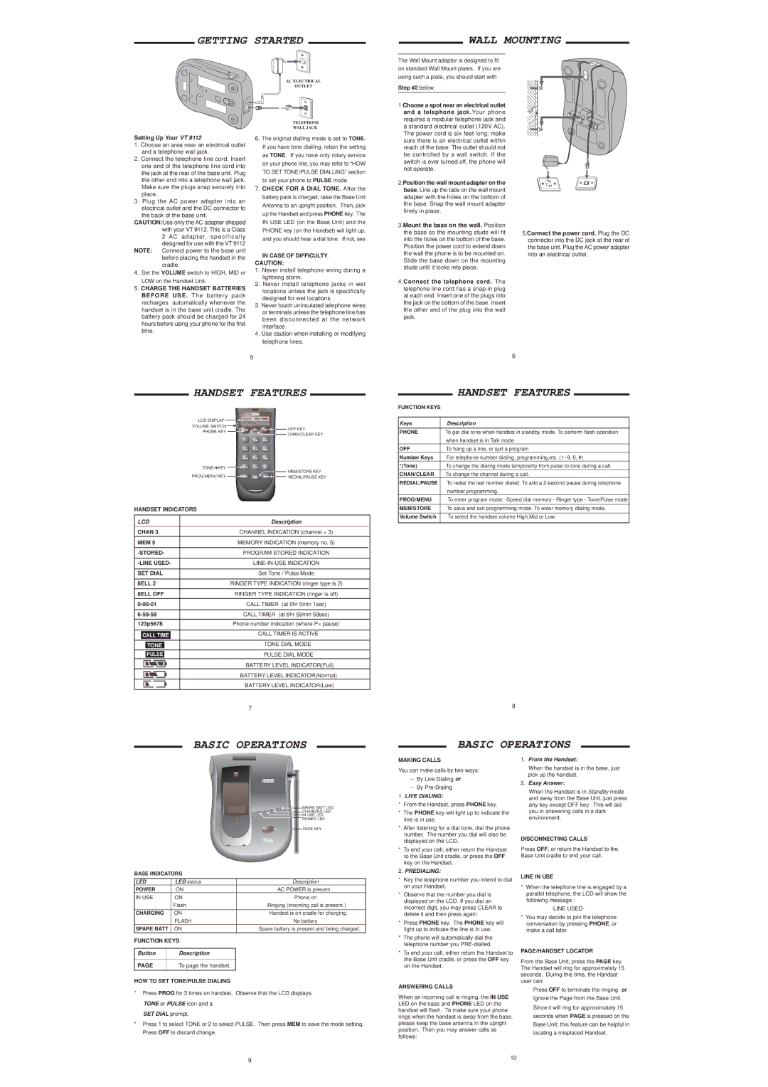
The Wall Mount adaptor is designed to fit on standard Wall Mount plates. If you are using such a plate, you should start with
Setting Up Your VT 9112
1.Choose an area near an electrical outlet and a telephone wall jack.
2.Connect the telephone line cord. Insert one end of the telephone line cord into the jack at the rear of the base unit. Plug the other end into a telephone wall jack. Make sure the plugs snap securely into place.
3.Plug the AC power adapter into an electrical outlet and the DC connector to
the back of the base unit. CAUTION:Use only the AC adapter shipped
with your VT 9112. This is a Class 2 AC adapter, specifically designed for use with the VT 9112
NOTE: Connect power to the base unit before placing the handset in the cradle.
4.Set the VOLUME switch to HIGH, MID or LOW on the Handset Unit.
5.CHARGE THE HANDSET BATTERIES BEFORE USE . The battery pack recharges automatically whenever the handset is in the base unit cradle. The battery pack should be charged for 24 hours before using your phone for the first time.
AC ELECTRICAL
OUTLET
TELEPHONE
WALL JACK
6.The original dialling mode is set to TONE. If you have tone dialling, retain the setting as TONE. If you have only rotary service on your phone line, you may refer to “HOW TO SET TONE/PULSE DIALLING” section to set your phone to PULSE mode.
7.CHECK FOR A DIAL TONE. After the battery pack is charged, raise the Base Unit Antenna to an upright position. Then, pick up the Handset and press PHONE key. The IN USE LED (on the Base Unit) and the PHONE key (on the Handset) will light up, and you should hear a dial tone. If not, see
IN CASE OF DIFFICULTY.
CAUTION:
1.Never install telephone wiring during a lightning storm.
2.Never install telephone jacks in wet locations unless the jack is specifically designed for wet locations.
3.Never touch uninsulated telephone wires or terminals unless the telephone line has been disconnected at the network interface.
4.Use caution when installing or modifying telephone lines.
Step #2 below.
1.Choose a spot near an electrical outlet and a telephone jack.Your phone requires a modular telephone jack and
astandard electrical outlet (120V AC). The power cord is six feet long; make sure there is an electrical outlet within reach of the base. The outlet should not be controlled by a wall switch. If the switch is ever turned off, the phone will not operate.
2.Position the wall mount adapter on the base. Line up the tabs on the wall mount adapter with the holes on the bottom of the base. Snap the wall mount adapter firmly in place.
3.Mount the base on the wall. Position the base so the mounting studs will fit into the holes on the bottom of the base. Position the power cord to extend down the wall the phone is to be mounted on. Slide the base down on the mounting studs until it locks into place.
4.Connect the telephone cord. The telephone line cord has a
wooden stud
wallboard
5.Connect the power cord. Plug the DC connector into the DC jack at the rear of the base unit. Plug the AC power adapter into an electrical outlet.
5
6 |
HANDSET FEATURES
LCD DISPLAY ![]()
![]()
![]()
![]()
![]()
![]()
![]()
![]()
![]()
VOLUME SWITCH ![]()
![]()
|
| HANDSET FEATURES |
|
FUNCTION KEYS |
|
| |
|
|
| |
|
|
| |
Keys | Description | ||
PHONE KEY
OFF KEY CHAN/CLEAR KEY
PHONE | To get dial tone when handset in standby mode. To perform flash operation |
| when handset is in Talk mode |
OFF | To hang up a line, or quit a program |
Number Keys | For telephone number dialing, programming,etc. (1~9, 0, #) |
TONE/![]() KEY
KEY ![]()
![]()
MEM/STORE KEY
PROG/MENU KEY ![]()
![]()
![]()
![]()
![]() REDIAL/PAUSE KEY
REDIAL/PAUSE KEY
HANDSET INDICATORS
LCD | Description | |||||
|
|
| ||||
CHAN 3 | CHANNEL INDICATION (channel = 3) | |||||
MEM 5 | MEMORY INDICATION (memory no. 5) | |||||
|
|
| ||||
PROGRAM STORED INDICATION | ||||||
|
| |||||
|
| |||||
SET DIAL | Set Tone / Pulse Mode | |||||
|
| |||||
8ELL 2 | RINGER TYPE INDICATION (ringer type is 2) | |||||
|
| |||||
8ELL OFF | RINGER TYPE INDICATION (ringer is off) | |||||
|
| CALL TIMER (at 0hr 0min 1sec) | ||||
|
|
|
| |||
|
| CALL TIMER (at 6hr 59min 59sec) | ||||
|
| |||||
123p5678 | Phone number indication (where P= pause) | |||||
|
|
|
| |||
|
|
|
|
| CALL TIMER IS ACTIVE | |
| CALL TIME |
| ||||
|
|
|
|
|
| |
|
|
|
|
| TONE DIAL MODE | |
|
| TONE |
|
| ||
|
|
|
|
|
|
|
|
|
|
|
|
|
|
|
| PULSE |
|
| PULSE DIAL MODE | |
|
|
|
|
|
| |
|
|
|
|
| BATTERY LEVEL INDICATOR(Full) | |
|
|
|
|
| BATTERY LEVEL INDICATOR(Normal) | |
|
|
|
|
| BATTERY LEVEL INDICATOR(Low) | |
7
BASIC OPERATIONS
*(Tone) | To change the dialing mode temporarily from pulse to tone during a call. |
CHAN/CLEAR | To change the channel during a call. |
REDIAL/PAUSE To redial the last number dialed. To add a | |
| number programming. |
PROG/MENU | To enter program mode; |
MEM/STORE | To save and exit programming mode. To enter memory dialing mode. |
|
|
Volume Switch | To select the handset volume High,Mid or Low. |
8
BASIC OPERATIONS
SPARE BATT LED |
CHARGING LED |
IN USE LED |
POWER LED |
PAGE KEY |
BASE INDICATORS
LED | LED status | Description | |
POWER | ON | AC POWER is present | |
IN USE | ON | Phone on | |
|
| Flash | Ringing (incoming call is present.) |
|
|
|
|
CHARGING | ON | Handset is on cradle for charging. | |
|
| FLASH | No battery |
SPARE BATT | ON | Spare battery is present and being charged. | |
FUNCTION KEYS |
| ||
|
|
|
|
Button |
| Description |
|
|
|
|
|
PAGE |
| To page the handset. |
|
HOW TO SET TONE/PULSE DIALING
*Press PROG for 3 times on handset. Observe that the LCD displays: TONE or PULSE icon and a
SET DIAL prompt.
*Press 1 to select TONE or 2 to select PULSE. Then press MEM to save the mode setting. Press OFF to discard change.
MAKING CALLS
You can make calls by two ways:
--By Live Dialing or
--By
1.LIVE DIALING:
*From the Handset, press PHONE key.
*The PHONE key will light up to indicate the line is in use.
*After listening for a dial tone, dial the phone number. The number you dial will also be displayed on the LCD.
*To end your call, either return the Handset to the Base Unit cradle, or press the OFF key on the Handset.
2.PREDIALING:
*Key the telephone number you intend to dial on your Handset.
*Observe that the number you dial is displayed on the LCD. If you dial an incorrect digit, you may press CLEAR to delete it and then press again
*Press PHONE key. The PHONE key will light up to indicate the line is in use.
*The phone will automatically dial the telephone number you
*To end your call, either return the Handset to the Base Unit cradle, or press the OFF key on the Handset.
ANSWERING CALLS
When an incoming call is ringing, the IN USE LED on the base and PHONE LED on the handset will flash. To make sure your phone rings when the handset is away from the base, please keep the base antenna in the upright position. Then you may answer calls as follows:
1.From the Handset:
When the handset is in the base, just pick up the handset.
2.Easy Answer:
When the Handset is in Standby mode and away from the Base Unit, just press any key except OFF key. This will aid you in answering calls in a dark environment.
DISCONNECTING CALLS
Press OFF, or return the Handset to the Base Unit cradle to end your call.
LINE IN USE
*When the telephone line is engaged by a parallel telephone, the LCD will show the following message :
*You may decide to join the telephone conversation by pressing PHONE, or make a call later.
PAGE/HANDSET LOCATOR
From the Base Unit, press the PAGE key. The Handset will ring for approximately 15 seconds. During this time, the Handset user can:
Press OFF to terminate the ringing or
Ignore the Page from the Base Unit.
Since it will ring for approximately 15
seconds when PAGE is pressed on the
Base Unit, this feature can be helpful in
locating a misplaced Handset.
9 | 10 |
|