OPERATION
WARNING: THE KETTLE AND ITS PARTS ARE HOT. USE CARE WHEN OPERATING, CLEANING AND SERVICING THE KETTLE.
Before operating, check the jacket water level by looking at the sight glass at the rear of the kettle with both upper and lower valves open. The water level should be at the midpoint of the sight glass. If water is below the recommended level or if it is murky, refer to Jacket Water Level, page 12. Also check the flue at the rear of the kettle for any obstructions before operating.
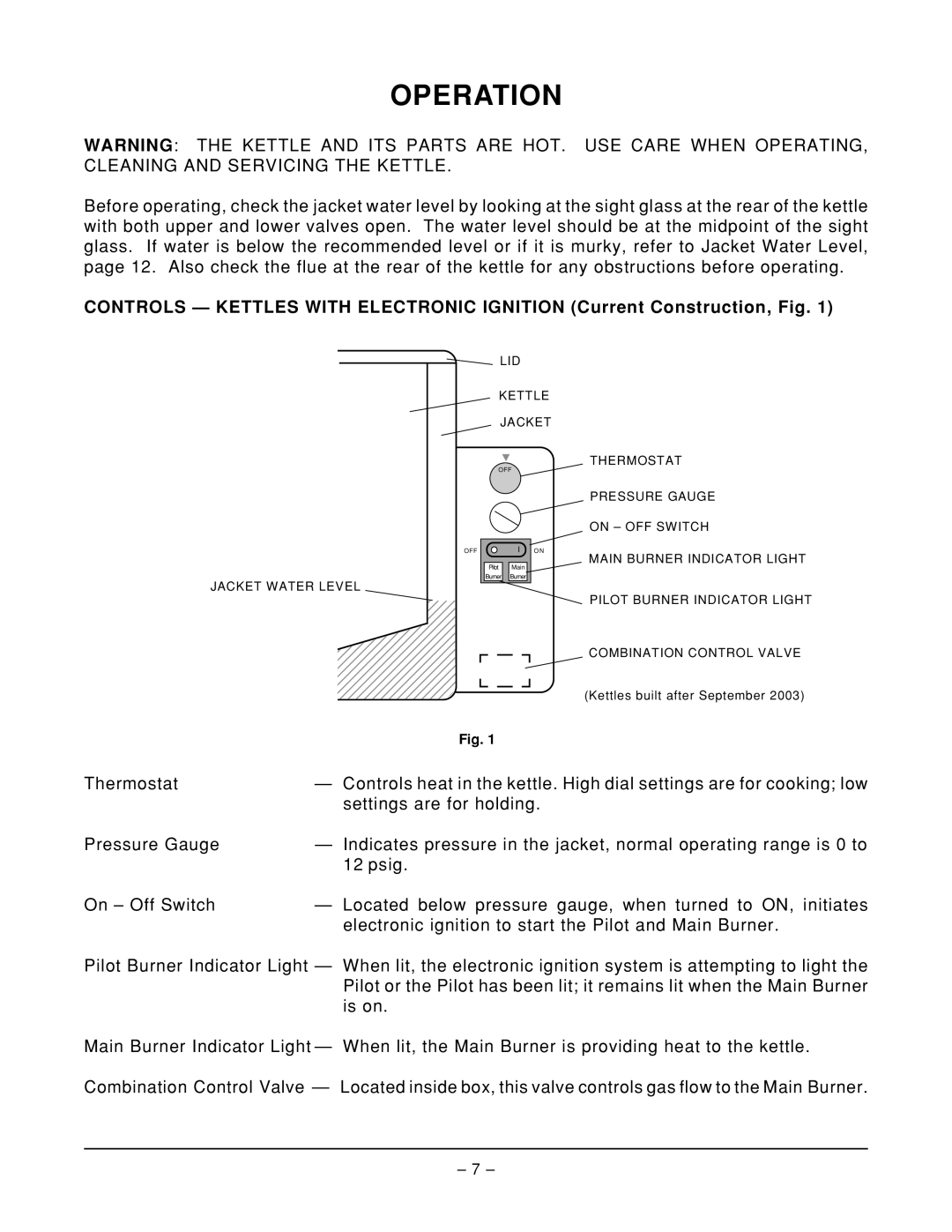
CONTROLS — KETTLES WITH ELECTRONIC IGNITION (Current Construction, Fig. 1)
LID
KETTLE
JACKET
THERMOSTAT
OFF
PRESSURE GAUGE
ON – OFF SWITCH
JACKET WATER LEVEL
OFF
23
Pilot Main Burner Burner
ON
MAIN BURNER INDICATOR LIGHT
PILOT BURNER INDICATOR LIGHT
COMBINATION CONTROL VALVE
(Kettles built after September 2003)
| Fig. 1 |
Thermostat | — Controls heat in the kettle. High dial settings are for cooking; low |
| settings are for holding. |
Pressure Gauge | — Indicates pressure in the jacket, normal operating range is 0 to |
| 12 psig. |
On – Off Switch | — Located below pressure gauge, when turned to ON, initiates |
| electronic ignition to start the Pilot and Main Burner. |
Pilot Burner Indicator Light — When lit, the electronic ignition system is attempting to light the Pilot or the Pilot has been lit; it remains lit when the Main Burner is on.
Main Burner Indicator Light — When lit, the Main Burner is providing heat to the kettle.
Combination Control Valve — Located inside box, this valve controls gas flow to the Main Burner.
– 7 –