ANCHORING STEAMER (Without Legs)
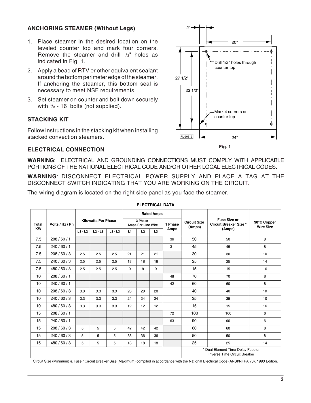
1.Place steamer in the desired location on the leveled counter top and mark four corners. Remove the steamer and drill 1/2" holes as indicated in Fig. 1.
2.Apply a bead of RTV or other equivalent sealant around the bottom perimeter edge of the steamer. If anchoring the steamer, this bottom seal is necessary to meet NSF requirements.
3.Set steamer on counter and bolt down securely with 3/8 - 16 bolts (not supplied).
STACKING KIT
2"
27 1/2"
23 1/2"
20"
Drill 1/2" holes through counter top
Mark 4 corners on counter top
Follow instructions in the stacking kit when installing stacked convection steamers.
ELECTRICAL CONNECTION
24" | |
|
Fig. 1
WARNING: ELECTRICAL AND GROUNDING CONNECTIONS MUST COMPLY WITH APPLICABLE PORTIONS OF THE NATIONAL ELECTRICAL CODE AND/OR OTHER LOCAL ELECTRICAL CODES.
WARNING: DISCONNECT ELECTRICAL POWER SUPPLY AND PLACE A TAG AT THE DISCONNECT SWITCH INDICATING THAT YOU ARE WORKING ON THE CIRCUIT.
The wiring diagram is located on the right side panel as you face the steamer.
ELECTRICAL DATA
|
|
|
| Rated Amps |
|
|
|
| ||
|
| Kilowatts Per Phase |
|
|
|
|
| Fuse Size or |
| |
|
|
| 3 Phase |
|
| Circuit Size | 90°C Copper | |||
Total | Volts / Hz / Ph | Amps Per Line Wire | 1 Phase | Circuit Breaker Size * | ||||||
(Amps) | Wire Size | |||||||||
KW |
|
|
|
|
| Amps | (Amps) | |||
| L1 - L2 L2 - L3 L1 - L3 | L1 | L2 | L3 |
|
| ||||
|
|
|
|
|
| |||||
7.5 | 208 / 60 / 1 |
|
|
|
|
|
| 36 | 50 | 50 | 8 |
|
|
|
|
|
|
|
|
|
|
|
|
7.5 | 240 / 60 / 1 |
|
|
|
|
|
| 31 | 45 | 45 | 8 |
|
|
|
|
|
|
|
|
|
|
|
|
7.5 | 208 / 60 / 3 | 2.5 | 2.5 | 2.5 | 21 | 21 | 21 |
| 30 | 30 | 10 |
|
|
|
|
|
|
|
|
|
|
|
|
7.5 | 240 / 60 / 3 | 2.5 | 2.5 | 2.5 | 18 | 18 | 18 |
| 25 | 25 | 14 |
|
|
|
|
|
|
|
|
|
|
|
|
7.5 | 480 / 60 / 3 | 2.5 | 2.5 | 2.5 | 9 | 9 | 9 |
| 15 | 15 | 16 |
|
|
|
|
|
|
|
|
|
|
|
|
10 | 208 / 60 / 1 |
|
|
|
|
|
| 48 | 70 | 70 | 8 |
|
|
|
|
|
|
|
|
|
|
|
|
10 | 240 / 60 / 1 |
|
|
|
|
|
| 42 | 60 | 60 | 8 |
|
|
|
|
|
|
|
|
|
|
|
|
10 | 208 / 60 / 3 | 3.3 | 3.3 | 3.3 | 28 | 28 | 28 |
| 40 | 40 | 10 |
|
|
|
|
|
|
|
|
|
|
|
|
10 | 240 / 60 / 3 | 3.3 | 3.3 | 3.3 | 24 | 24 | 24 |
| 35 | 35 | 10 |
|
|
|
|
|
|
|
|
|
|
|
|
10 | 480 / 60 / 3 | 3.3 | 3.3 | 3.3 | 12 | 12 | 12 |
| 15 | 15 | 16 |
|
|
|
|
|
|
|
|
|
|
|
|
15 | 208 / 60 / 1 |
|
|
|
|
|
| 72 | 100 | 100 | 6 |
|
|
|
|
|
|
|
|
|
|
|
|
15 | 240 / 60 / 1 |
|
|
|
|
|
| 63 | 90 | 90 | 6 |
|
|
|
|
|
|
|
|
|
|
|
|
15 | 208 / 60 / 3 | 5 | 5 | 5 | 42 | 42 | 42 |
| 60 | 60 | 8 |
|
|
|
|
|
|
|
|
|
|
|
|
15 | 240 / 60 / 3 | 5 | 5 | 5 | 36 | 36 | 36 |
| 50 | 50 | 8 |
|
|
|
|
|
|
|
|
|
|
|
|
15 | 480 / 60 / 3 | 5 | 5 | 5 | 18 | 18 | 18 |
| 25 | 25 | 14 |
|
|
|
|
|
|
|
|
|
|
|
|
|
|
|
|
|
|
|
|
|
| * Dual Element |
|
|
|
|
|
|
|
|
|
|
| Inverse Time Circuit Breaker |
|
Circuit Size (Minimum) & Fuse / Circuit Breaker Size (Maximum) compiled in accordance with the National Electrical Code (ANSI/NFPA 70), 1993 Edition.
3
