260600, 260597 specifications
Wayne-Dalton is renowned for its innovative approach to garage door design and technology, and models 260600 and 260597 exemplify this commitment to quality and functionality. These models are part of the brand's comprehensive line of insulated steel garage doors, which are designed to provide efficiency, durability, and aesthetic appeal.One of the primary features of the Wayne-Dalton 260600 and 260597 models is their exceptional insulation capabilities. They are constructed using a double-section steel design with a polyurethane core, offering an impressive R-value that helps maintain temperature control within the garage. This is particularly beneficial for homeowners looking to reduce energy consumption and improve energy efficiency throughout their property.
Both models come in a variety of sizes and customizable designs, allowing homeowners to select the perfect fit for their unique garage structure. The 260600 and 260597 doors are available in multiple color options and finishes, ensuring they complement the overall aesthetic of any home. Additionally, Wayne-Dalton provides several design options, including traditional raised panels, modern flat panels, and decorative windows, allowing homeowners to tailor their garage door to their personal style.
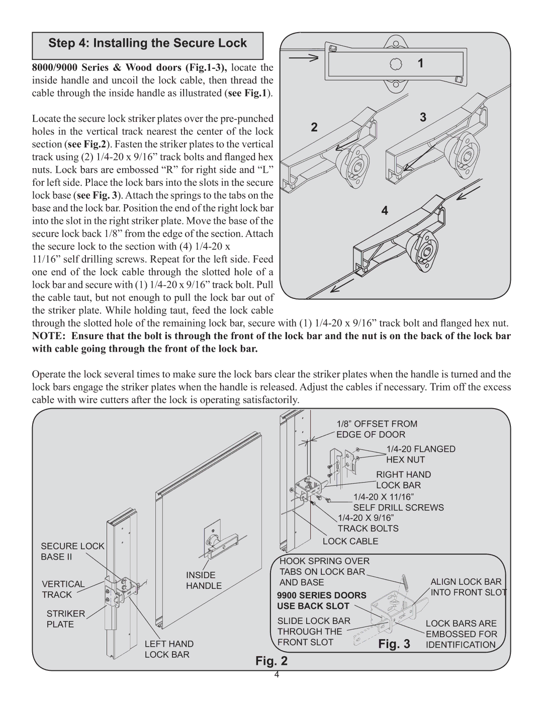
The technological advancements in these models do not stop at aesthetics and insulation. Wayne-Dalton has integrated advanced safety features into the design of the 260600 and 260597. These garaged doors are equipped with innovative safety measures such as pinch protection and a robust locking mechanism, ensuring that family members and belongings remain safe.
Installation is simplified with the inclusion of Wayne-Dalton’s thorough instructions and provided hardware. The doors are also constructed to withstand the elements, thanks to the use of high-quality materials that resist rust and corrosion. Additionally, Wayne-Dalton offers a variety of garage door openers that integrate seamlessly with these models, enhancing their functionality.
In summary, the Wayne-Dalton 260600 and 260597 garage doors stand out due to their superior insulation, customizable design options, advanced safety features, and durable construction. These models exemplify Wayne-Dalton’s dedication to providing homeowners with reliable, efficient, and stylish garage solutions that cater to a wide range of preferences and requirements. Whether for residential or commercial use, these doors are a smart investment that combines quality and cutting-edge technology.

