|
| Jamb Bracket Schedule |
| Required Tools |
| IMPORTANT | MAINTENANCE AND PAINTING | |||||
|
|
|
|
|
|
|
|
|
|
| INSTRUCTION FOR | |
| BMW QUICK INSTALL TRACK - STANDARD LIFT |
|
|
|
|
| SAFETY NOTICES |
| ||||
DOOR | 1ST SET | 2ND SET | 3RD SET |
|
|
|
| |||||
HEIGHT | JAMB |
| JAMB |
| JAMB |
|
|
|
|
| MAINTENANCE | |
BRACKET | POSITION BRACKET POSITION BRACKET | POSITION | (1) 7/16” Hex |
| Sockets (7/16”, |
| P.O. Box 67 | |||||
| Gloves |
| ||||||||||
7’ 0” 76” |
|
|
|
|
|
| Head Driver | 1/2”, 9/16”) | (1) Screw Driver | Mt. Hope, Ohio 44660 | While | |
TRACK | QIJB - 3 | BOTTOM | QIJB | MIDDLE | NOT APPLICABLE |
|
|
| Read these instructions carefully before attempting installation. If in question about any of the | basis. Some discoloration of the finish may occur when a door has been exposed to | ||
(1930mm) |
|
|
|
|
|
|
|
|
| (Phillips Blade) | ||
|
|
|
|
|
|
|
|
|
|
| procedures, do not perform the work. Instead, have a qualified door agency do the installation or | period of time. Slight chalking may also occur as a result of direct exposure to sunlight. Cleaning the door will |
|
|
|
|
|
|
|
|
|
|
| repairs. | generally restore the appearance of the finish. To maintain an aesthetically pleasing finish of the garage door, an |
|
|
|
|
|
|
| 2ND |
|
|
|
| annual washing of the door is recommended. A mild solution of detergent and water will aid in the removal of most |
|
|
|
|
|
|
|
|
|
| 1. Wear protective gloves during installation to avoid possible cuts from sharp metal edges. | dirt. The following solution mixture is recommended: | |
|
|
|
|
|
|
| SET |
|
|
| One cup of Tide™, or other common detergents, which contain less than 0.5% phosphate, dissolved into five gallons | |
|
|
|
|
|
|
|
|
|
|
| ||
|
|
|
|
|
|
| (1) Step Ladder |
|
| (1) Screw Driver | 2. It is always recommended to wear eye protection when using tools, otherwise severe or fatal eye | of warm water. |
|
|
|
|
|
|
|
| (1) Socket Wrench | CAUTION: NEVER MIX CLEANSERS OR DETERGENTS WITH BLEACH. | |||
|
|
|
|
|
|
| (1) Electric Drill | (Standard Blade) | injury could result. | |||
|
|
|
|
|
|
|
|
|
|
| ||
|
|
|
|
|
|
|
| With Clutch |
|
|
| SURFACE PREPARATION FOR PAINTING |
|
|
|
|
|
|
|
|
|
|
| 3. Avoid installing your new door on windy days. Door could fall during the installation causing severe | |
|
|
|
|
|
|
|
|
|
|
| Wax on the surface must be removed or paint peeling/flaking will result. To remove this wax, it will be | |
|
|
|
|
|
|
|
|
|
|
| or fatal injury. | necessary to lightly scuff the surface with a fine steel wool pad, saturated with soapy water. A final wipe and rinse |
|
|
|
|
|
|
| (1) Level (2’ Minimum Length) |
|
|
| 4. If the door is to be electrically operated at any time, all pull ropes MUST be removed to prevent | should be done with clean water only, to remove any loose particles and any soapy film residue. |
|
|
|
|
|
|
|
|
| Surface scratches, which have not exposed the metal substrate, can be lightly buffed or sanded with 0000 | |||
08/03/2009rev 3 | 316584 .NO PART | .Corp | © |
|
| .y | notwillsupplibe | ednotif | nssarece |
|
|
|
|
| |||
|
| NOT | EDe:ndingpe | on thdoore | mod esoml, partse | list | ed | |||||
| 274884 # ROP PULL 60” (y) |
|
| E |
|
|
| B | ||||
| 100362 # | SCR 6 # (x) |
| EWEYE |
|
|
| |||||
|
|
|
|
|
|
|
| |||||
Y | S SOLD | SUPPORTw() ARE |
|
|
| PARATE | EL |
| ||||
| 302879 # SHOWN)L (v) owadroom(NOTHe | K it |
|
|
|
|
| |||||
300551 # | WRAP DRUM RIGHT (U) |
|
|
| y |
|
|
|
| D | ||
| 300550 # | WRAPLDRUM(T) | EFT |
|
|
|
|
|
|
| ||
| 296246 # | C (S) BRACKENTER | .ASMET |
|
|
|
|
| ||||
Y | S SOLD | (R)OPidrive™ RATORE |
| PARATE | EL | |||||||
| G WORM282335 TOOTH# 36Q( ) |
|
|
| ARE |
|
|
|
|
| ||
|
| COUNT | (DOUBLCO(LH)ER .ASMVE 287721R # | SPRING)E |
|
|
|
| ||||
| 287722 # | COUNT (P) |
| CO(RH)E | .ASMVE R |
|
|
|
|
|
| |
| 284035 # | COUNT (O) |
| GER | ARE |
|
|
|
|
|
| |
|
| INGLLOOS(SHAFT(N) WINDINGE280066 # | SPRING)E |
|
| D1 | ||||||
| 282340 # | BRACK(M) NDE | (RH)ET |
|
|
|
| |||||
|
|
|
|
|
|
| ||||||
| 282937 # | BRACK(L) NDE | (LH)ET |
|
|
|
|
|
| |||
| 280086 # | (PAIR)CBL (K).ASM /DRUME |
|
|
|
|
|
|
| |||
Y |
| ASSTOR(J1) | QMASTUE TUBER | E |
| MBLE |
|
|
| |||
|
| Safety Glasses | severe or fatal injury to children who may become entangled in the rope. Any locking mechanism | steel wool or No. 400 sand paper to create a smoother surface. Care must be taken to not expose the substrate under | |
|
| MUST be removed or made inoperative in the unlocked position.. | the paint (see Note No. 2). Once the substrate is exposed, the likelihood for rusting is greatly increased. See the | ||
1ST |
| (1) 7/16” Wrench |
| ||
|
|
| following paragraph if metal substrate is observed. | ||
SET | (1) Hammer |
|
| 5. Operate door ONLY when properly adjusted and free of obstructions. | The exposed substrate must be treated to prevent rust from forming (see Note No. 2). Sand the exposed |
|
|
| |||
|
|
|
| area lightly and paint with a high quality metal primer, specifically intended for galvanized surfaces, to protect the | |
|
|
|
|
| |
|
|
|
| 6. Should the door become hard to operate or completely inoperative, a qualified door agency should | area from corrosion. Follow drying time on primer can label before applying topcoat. |
|
|
|
| The surface of the | |
(1) Pliers |
|
|
| correct the problem to prevent damage to the door or serious personal injury. | not adhere to it (see Note No. 2). It is advisable to test in an inconspicuous area, to evaluate adhesion. If poor |
|
|
| Saw Horses For Supporting | 7. DO NOT PERMIT children to play with the garage door or the electrical controls. Severe or fatal | adhesion is observed, surface preparation for painting the factory- applied finish, must be repeated until desired |
NOTE: Jamb brackets are stamped for identification. | (1) Tape Measure | (2) Locking Pliers | results are achieved. Again, care must be taken to not expose the substrate under the paint. | ||
Sections During Assemblies | injury could result, should the child become entrapped between the door and the floor. |
|
PAINTING
8. To prevent severe or fatal injury, avoid standing in the open doorway or walking through the doorway Note: It is NOT recommend that you paint your door any dark color, this may lead to higher surface |
arts | List | or qeMuastNOTeTrwith™SeeE : idriPve™ | RBALANCE | ||
|
|
|
|
| |
|
|
| TOR QCOUNTEMAST R™E | ||
FLAGANGL .T.A285215.F15” R# (I) SHOWN) (NOT | x |
|
| |||
|
| |||||
FLAGANGL .T.A.F28521415” L (H)# SHOWN) (NOT |
| |||||
240383 # | FLAGANGLQ.I7/8”)15”. |
|
|
|
| |
| 15”240382LFLAGANGL(F) # Q.I. | FT,E | ||||
PAIR 1 | TRACK HORIZONTALE( ) |
|
|
| G | |
| 297925 #(D1)BRACKQ6JI- AMBJ | ET | ||||
|
| |||||
| 297922 # | (D)BRACKQ3JI- | AMBJ | ET |
|
|
PAIR 1 | TRACK(C)RTICALVE | E |
|
|
| |
154489 # | ROLL (B) | ER |
|
|
| |
| BRACK298386TOP# LHR (A1) | (RIGHT)ET |
|
| ||
| BRACK TOP298387LHR#(A) |
| (LET FT)E |
| ||
ES YST EM
A1
C ![]() F
F
a | c |
| e |
|
|
|
| i | Stud Plate | while the door is moving. | temperatures resulting in gaps between the stiles and rails of your door section(s). | |||
5/16” x | 1/4” x 2” Slotted Hex Head Lag Screw |
| #266102 |
| After the surface has been properly prepared it must be allowed to dry thoroughly, then coated immediately with a | |||||||||
Hex Nut |
|
| ||||||||||||
| #100279 |
| #300723 | #314937 | g #315760 |
|
|
| 9. Door is constantly under EXTREME SPRING TENSION. To prevent possible severe or fatal injury, | premium quality latex house paint. Follow the paint label directions explicitly. Oil base, or solvent base paints are | ||||
|
|
|
|
|
|
|
|
|
|
| removal, installation, adjustments or repairs, ESPECIALLY to SPRING ASSEMBLIES, CENTER | not recommended. Please note that if substrate is exposed and not properly primed, painting with latex paint may | ||
|
|
|
|
|
|
|
|
|
|
| cause accelerated rusting of the steel in the exposed area. |
| ||
|
|
|
|
|
|
|
|
|
|
| ANCHOR BRACKETS, BRACKET BOLTS, CABLE DRUMS, BOTTOM CORNER |
| ||
|
|
|
|
|
|
|
|
|
|
| NOTES: |
| ||
|
|
|
|
|
|
|
|
|
|
| BRACKETS, SHEAVES, CABLES, ETC., should ONLY be performed by qualified door service | 1. | Repainting of finish painted steel doors cannot be warranted, as this condition is totally beyond the door | |
|
|
|
|
|
|
|
|
|
|
| people. | manufacturer’s control. |
| |
|
|
|
|
|
|
|
|
|
|
|
| 2. | If the finish painted steel door surface has a textured surface representing wood grain, stucco, etc., this step | |
|
|
|
|
|
|
|
|
|
|
| 10. Check all bolted connections monthly during the lifetime of the door to prevent damage or severe/ | should not be attempted as danger of exposing substrate is greatly increased. |
| |
|
|
|
| 1/4” x |
|
|
|
|
| fatal injury caused by loose connections. | 3. | Consult a professional coatings contractor if in doubt about any of the above directions. | ||
b | 5/16”- Flat Washer |
| d Screw | f |
|
|
|
|
|
| 4. | Follow directions explicitly on the paint container labels for proper applications of coatings and disposal of | ||
| #236565 | Lag Screw |
|
|
|
|
| 11. It is recommended that doors 12’ 0” wide and over be installed by two person, to avoid possible | containers. Pay particular attention to acceptable weather and temperature conditions in which to paint. | |||||
#100370 |
|
|
| #315759 |
|
|
|
|
|
| DÉCOR LITES ACRYLIC GLAZING CLEANING INSTRUCTIONS: | |||
|
|
|
|
|
| h |
|
| 1/4” | injury. | 1. | |||
|
|
|
|
|
| j | Clean acrylic glazing with nonabrasive soap or detergent and plenty of water. Use your bare hands to feel and | |||||||
|
|
|
|
|
| Track Bolt | 12. Definition of key words used in this manual: | |||||||
|
|
|
|
|
| (Disconnect Handle) | dislodge any caked on particles A soft, | |||||||
|
|
|
|
|
|
| #296940 |
| #200527 | WARNING! — Indicates a potentially hazardous situation which, if | use hard or rough cloths that will scratch the acrylic glazing. Dry glazing with a clean damp chamois. | |||
|
|
|
|
|
|
|
|
|
| |||||
|
|
|
|
|
|
|
|
|
|
| ||||
|
|
|
|
|
|
|
|
|
|
| not avoided, could result in severe or fatal injury. | 2. | Kerosene may be used to remove grease and oil. When using kerosene for cleaning purposes, make sure that you | |
|
|
|
|
|
|
|
|
|
|
| IMPORTANT! — Required step for safe and proper door operation. | are familiar with it’s properties, using it only in a well ventilated area away from any sources of sparks and/or fire. | ||
|
|
|
|
|
|
|
|
|
|
| 3. DO NOT USE: Window cleaning fluids, scouring compounds, gritty cloths, gasoline, or solvents such | |||
|
|
|
|
|
|
|
|
|
|
| NOTE: — Information assuring proper installation of the door. | |||
|
|
|
|
|
|
|
|
|
|
| as alcohol, acetone, carbon tetrachloride, etc. | © Copyright 2009 | ||
|
|
|
|
|
|
|
|
|
|
| © Copyright 2009 |
|
| |
...CONTINUED INSTALLATION INSTRUCTIONS |
|
| ALTERNATE INSTALLATIONS |
|
|
|
| ||||||
18 | WARNING! Prior to winding or making adjustments to the springs, ensure |
|
|
| 12A |
| 5500/9700 ESTATE™ | ||||||
Otherwise the spring fittings may release from spring if not wound in the proper | If you are not installing the idrive™ operator on your garage door, you must install the center bracket bushing assembly. Follow these instructions for a |
| |||||||||||
you’re winding in the proper direction as stated in the Installation Instructions. | 12A |
|
|
|
|
|
|
|
|
| LIFETIME LIMITED WARRANTY | ||
direction and could result in severe or fatal injury. | springs come lubricated and |
|
| ||||||||||
|
|
|
|
| |||||||||
IMPORTANT! DO NOT USE IMPACT GUN TO WIND SPRING(S) | torque tube, from the right hand side, toward the center. Shake the TorqueMaster™ tube gently to extend the winding shafts out about 5” on both ends. Single spring TorqueMaster will only have the right hand |
|
|
| |||||||||
Beginning with the right hand side. Press and hold in the canoe clip. Ensure the cable is in the first groove of the drum. | spring. Slide center bracket bushing assembly from the right side to the center of the torque tube. |
|
|
|
|
|
| ||||||
Using an electric drill (high torque gear reduced to 1300 RPM preferred) with a 7/16” socket, carefully rotate right hand | IMPORTANT! Right and left hand is always determined from inside the building looking out. |
|
| 12B |
|
|
| ||||||
|
|
|
|
| P.O. Box 67, Mt. Hope, Ohio 44660 | ||||||||
winding bolt clockwise, until counter shows | 12B |
|
|
|
|
|
|
|
|
| |||
left hand side counterbalance cable. Repeat step 18 and 19 for left side. |
|
|
|
|
|
| TYPICAL TROLLEY OPERATOR INSTALLATION | Subject to the terms and conditions contained in this Lifetime Limited Warranty, | |||||
When installing a DoorMaster™ operator replace the bushing with the drive gear (located in DoorMaster™ |
|
| |||||||||||
NOTE: Single spring applications require no spring winding on the left hand side. |
|
| If you are installing an electric operator on your door, the following information is pro- | which is described at the top of this page, for as long as you own the door against: | |||||||||
Ensure counterbalance cable tension is equal for both sides prior to fully winding spring(s) to appropriately 15 1/2 turns | package). |
|
|
|
|
|
| (i) | Peeling, cracking, or chalking of the original | ||||
|
|
|
|
|
| vided to ensure proper function of | your door/operator installation. Figure below shows | plied coating or in the application of the original | |||||
for solid sections, or 15 turns for glazed top sections. Carefully rotate the winding bolt head clockwise until the counter |
|
|
|
|
|
|
| ||||||
|
|
|
|
|
|
| a typical means of connecting the operator arm to the operator stile located in the center | not been subjected to adverse atmospheric conditions or contaminates (such as salt water or other marine environment, or to toxic or abrasive substances, | |||||
shows the correct number of turns for your door. Repeat for the opposite side on double spring TorqueMaster™ systems. |
|
|
|
|
|
|
| ||||||
|
|
|
|
|
|
| of the top section. |
|
| including those in the air); (b) have been maintained in compliance with Manufacturer’s recommendations; and (c) have not been subject to physical abra- | |||
If door raises off the floor remove 1/2 - 1 full turn from each spring before proceeding. After spring is wound, hold the |
|
|
|
|
|
|
|
|
| sion, impacted by a hard object, or have been punctured. | |||
|
|
|
|
| 16 |
|
|
|
| ||||
lock nut (in back of end bracket) stationary with a 7/16” wrench while rotating the winding bolt clockwise until snug. |
|
|
|
|
|
|
|
|
| (ii) | The door becoming inoperable due to | ||
|
|
|
|
|
|
|
|
|
|
|
| ||
Tightening of the lock nut prevents spring from unwinding. Repeat for opposite side if necessary. |
|
|
|
|
|
|
|
|
|
| ting, or other deterioration of the steel skin, or due to structural failure caused by separation or degradation of the foam insulation. | ||
|
|
|
|
|
|
|
|
|
| The Manufacturer warrants the garage door hardware (except springs) and the tracks of the | |||
IMPORTANT! Adjustments to the recommended number of turns may be required. |
|
|
|
|
|
|
|
|
|
| |||
|
|
|
|
|
|
| BRIDGE POINT |
|
| door, against defects in material and workmanship, subject to all the terms and conditions below. | |||
AFTER REAR SUPPORTASSEMBLY IS COMPLETE, check door balance. If door raises off the floor under spring tension |
|
|
|
|
|
|
|
|
| The Manufacturer warrants those component parts of the door not covered by the preceding provisions of this Lifetime Limited Warranty | |||
16 |
|
|
|
|
|
|
|
|
| ||||
alone, then reduce turns until door will rest on floor. A “hot” door such as this can cause idrive™ operation problems. |
|
|
|
|
|
|
|
| TYPICAL OP- | against defects in material and workmanship for a period of ONE (1) YEAR from the date of installation. | |||
19 |
| To locate the center bracket, mark the header halfway between the flagangles and level the TorqueMaster tube. Fas- |
|
| TYPICAL OPERATOR |
| ERATOR ARM | The Manufacturer warrants the | |||||
|
|
|
| installation for TWO (2) YEARS. The factory attached stiles are warranted against peeling, cracking, chalking, or delamination from the time of installation | |||||||||
| ten the metal bracket to the header using (2) 1/4” x |
|
|
|
| BRACKET (SUPPLIED |
| (SUPPLIED WITH | |||||
Drum wraps are identified as right and left. To install, place the drum wrap over the cable drum and under the idrive™ |
|
|
|
|
| for TWO (2) YEARS. If the door is | |||||||
|
| OPTIONAL ACCESSORY INSTALLATIONS |
|
| WITH DOOR) |
| OPERATOR) | After a period of TWENTY (20) YEARS, from time of installation, replacement of Lifetime Limited Warranty materials will be | |||||
disconnect cable (if installed). Align the outside flange over the outside edge of the cable drum and push the drum wrap |
|
|
|
|
|
|
| per cent of Manufacturer’s published list pricing at time of claim, and you must pay this amount. | |||||
down onto the cable drum. | STEP PLATES |
|
| (OUTSIDE) |
| (INSIDE) | SEE OPERATOR BRACKET |
|
| This Limited Warranty is extended only to the person who purchased the product and continues to own the premises (where the door is | |||
20 |
| Raise the door to a comfortable working height and secure with locking pliers to the track. Locate the | DRILL THROUGH |
|
| INSTRUCTIONS FOR DE- |
|
| installed) as his/her primary residence (“Buyer”). This Limited Warranty does not apply to residences other than primary, or to commercial or industrial | ||||
|
|
|
|
| installations, or to installations on rental property (even when used by a tenant as a residence). This Limited Warranty is not transferable to any other person | ||||||||
Hold the door down to prevent it from rising unexpectedly in the event the spring(s) was overwound and carefully re- | center stile on the bottom section of the door. Using the | SECTION WITH A 7/16” |
| TAILS ON INSTALLATION |
|
| |||||||
|
|
| (even when the premises is sold), nor does it extend benefits to any other person. As a result this Limited Warranty does NOT apply to any person who | ||||||||||
move the locking pliers from the vertical tracks. Raise the door until the top section and half of the next section are in a | a template, drill (2) 7/32” (6mm) dia. holes through the section. Using the previously drilled holes as a | (11mm) DIA. DRILL BIT |
| Installation Tips: |
| purchases the product from someone other than an authorized | |||||||
horizontal position. Do not raise door any further since rear of horizontal track is not yet supported. | guide, enlarge the holes from outside the door to 7/16” (11mm) dia. and assemble the outside and inside |
|
|
| (2) |
| The Manufacturer will not be responsible for any damage attributable to improper storage, improper installation, or any alteration of the door | ||||||
|
|
| 1. Follow the installation instructions supplied with your operator. |
| |||||||||
step plates to the section using (2) #8 x |
|
|
|
| or its components, abuse, damage from corrosive fumes or substances, salt spray or saltwater air, fire, Acts of God, failure to properly maintain the door, | ||||||||
WARNING! |
|
|
|
| |||||||||
the inside of the door. |
|
|
|
| #8 x | 2. Reinforce top section prior to attaching operator. |
| or attempt to use the door, its components or related products for other than its intended purpose and its customary usage. This Limited Warranty does not | |||||
RAISING DOOR FURTHER CAN RESULT IN DOOR FALLING AND CAUSING SEVERE OR FATAL INJURY. | WARNING! To avoid serious injury to fingers or hands, |
|
|
| SCREWS | 3. Install trolley rail 1/2” to 1” (13 - 25 mm) above high arc of top section of the door. | cover ordinary wear. This Limited Warranty will be voided if the original finish is painted over, unless Manufacturer’s preparation and painting instructions are | ||||||
Now clamp a pair of locking pliers to the vertical tracks just above the second roller on one side, and just below the second |
|
|
| 4. Mount operator to ceiling so that 1” to | |||||||||
|
|
|
| followed explicitly. This Limited Warranty will be voided if any holes are drilled into the door, other than those specified by the Manufacturer. | |||||||||
|
|
|
|
|
|
|
|
|
|
|
| ||
roller on the other side. This will prevent the door from raising or lowering while installing the rear support. Using | never place fingers or hands between door sections and track |
|
|
|
| between trolley rail and top section when door is fully open (trolley rail will slope | THIS LIMITED WARRANTY COVERS A CONSUMER PRODUCT AS DEFINED BY THE | ||||||
|
|
|
| IMPLIED (INCLUDING BUT NOT LIMITED TO THE WARRANTY OF MERCHANTABILITY OR FITNESS FOR A PARTICULAR PURPOSE) WILL EXTEND BEYOND | |||||||||
perforated angle, 2” lag screws and 5/16” bolts with nuts (may not be supplied), fabricate rear support for horizontal | when operating door. Always use step plate when manually oper- |
|
|
|
| down towards rear). |
|
| THE TIME PERIOD SET FORTH IN UNDERSCORED BOLD FACE TYPE IN THIS LIMITED WARRANTY, ABOVE. | ||||
tracks. Attach horizontal tracks to the rear supports with | ating door. |
|
|
| No.6 |
| 5. The operator bracket must be mounted to the operator muntin on the top section. | • | Some States do not allow limitations on how long an implied warranty lasts, so the above limitations may not apply to you. | ||||
Horizontal tracks must be level and parallel with door. | PULL ROPE |
|
|
|
| 6. Attach operator rail securely to spring pad. |
| Any claim under this Limited Warranty must be made in writing, within the applicable warranty period, to the dealer from which the product | |||||
WARNING! | Attach No. 6 screw eye to wood jamb approximately 48” - 50” (1220 - 1270 mm) off the floor. Use | screw |
| 7. Attach operator to ceiling using perforated angle. |
| was purchased. Unless the dealer is no longer in business, a written claim to the Manufacturer will be the same as if no claim had been made at all. | |||||||
eye |
|
| the product on site, or Buyer may be required to return the product to the Manufacturer at Buyer’s expense. Buyer agrees to cooperate with any representa- | ||||||||||
| 8. IMPORTANT! ANGLE MUST BE ATTACHED TO FRAMING MEMBER(S) | ||||||||||||
|
|
|
|
|
| At the Manufacturer’s option, pursuant to the dealer having notified the Manufacturer of a warranty claim, a service representative may inspect | |||||||
KEEP HORIZONTAL TRACK PARALLEL AND WITHIN 3/4” OF DOOR EDGE, OTHERWISE DOOR COULD | (1) |
|
|
| WARNING! OPERATOR MUST BE TESTED AT TIME OF INSTAL- | If the Manufacturer determines that the claim is valid under the terms of this Limited Warranty, the Manufacturer will cause the defective | |||||||
FALL, RESULTING IN SEVERE OR FATAL INJURY. | to both the screw eye and the pull rope clip. |
|
|
|
| ||||||||
|
|
|
|
|
|
|
|
|
|
|
| tive of the Manufacturer and to give such representative full access to the product with the claimed defect and full access to the location of its installation. | |
Permanently attach the vinyl weather stripping to both door jambs and the header, Fig. 6C. Now, lift the door and check | WARNING! DO NOT INSTALL PULL ROPE ON DOORS WITH ELECTRIC OP- |
| rope | LATION AND MONTHLY THERE AFTER, ACCORDING TO THE MANUFAC- | product to be repaired or replaced. The decision about the manner in which the defect will be remedied will be at the discretion of the Manufacturer, subject | ||||||||
| TURER’S INSTRUCTIONS TO ENSURE THAT ALL SAFETY FEATURES ARE | to applicable law. THE REMEDY WILL COVER ONLY MATERIAL. THIS LIMITED WARRANTY DOES NOT COVER OTHER CHARGES, SUCH AS FIELD SERVICE | |||||||||||
it’s balance. Adjust, if door lifts by itself (also hard to pull down) or if door is difficult to lift (too easy to pull down). | ERATORS. CHILDREN MAY BECOME ENTANGLED IN THE ROPE RESULTING SEVERE |
|
|
| |||||||||
Anytime spring adjustments are made you must loosen the lock nuts to begin with and retighten both lock nuts afterwards. |
|
|
| FUNCTIONING CORRECTLY. FAILURE TO PERFORM THESE TESTS AND | LABOR FOR REMOVAL, INSTALLATION, PAINTING, SHIPPING, ETC. | ||||||||
OR FATAL INJURY. | INSIDE SIDE LOCK |
| TRACK | END STILE | (4) | Any repairs or replacements arranged by Manufacturer will be covered by (and subject to) the terms, conditions, limitations and exceptions of | |||||||
To adjust spring(s), only add or remove 1/4 turn on the counter reading at a time. Adjust both sides equally. |
| MAKE ANY NECESSARY ADJUSTMENTS/REPAIRS CAN RESULT IN SEVERE | |||||||||||
|
|
| (2) |
| SELF DRILLING | this Limited Warranty; provided, however, that the installation date for the repaired or replaced product will be deemed to be the date the original product | |||||||
IMPORTANT! Do not add or remove more than 1 spring turn from specified amount. |
|
| Select desired side of door for lock placement. Locate the striker plates over the | TRACK BOLTS |
| SCREWS | OR FATAL INJURY. |
|
| was installed, and this Limited Warranty will expire at the same time as if there had been no defect. If a claim under this Limited Warranty is resolved in a | |||
|
|
|
|
|
| ||||||||
If the door still does not operate easily, lower the door into the closed position, UNWIND SPRING(S) TO ZERO, and | d | 2” |
|
|
|
|
|
| manner other than described in the immediately preceding paragraph, then neither this Limited Warranty nor any other warranty from the Manufacturer will | ||||
recheck the following items: | of the lock(second) section. Fasten the stiker plate to the vertical track using (2) |
|
|
|
| 8 |
| cover the repaired or replaced portion of the product. | |||||
| STRUT |
|
|
|
|
| THE REMEDIES FOR THE BUYER DESCRIBED IN THIS LIMITED WARRANTY ARE EXCLUSIVE and take the place of any other remedy. The li- | ||||||
1.) Check the door for level. |
|
|
|
|
|
|
| ||||||
|
| in approximately 1/8” from the edge of the section. Ensure that the lock is square |
|
|
|
|
|
| ability of the Manufacturer, whether in contract or tort, under warranty, product liability, or otherwise, will not go beyond the Manufacturer’s obligation to re- | ||||
2.) Check the TorqueMaster™ tube and flagangles for level and plumb. |
|
|
|
|
| 6 |
|
| |||||
|
| with the section and the lock bolt aligns with the striker plate. Secure the lock to |
|
|
|
|
| pair or replace, at its option, as described above. THE MANUFACTURER WILL NOT UNDER ANY CIRCUMSTANCES BE LIABLE FOR SPECIAL, INCIDENTAL, | |||||
3.) Check the distance between the flagangles - must be door width plus |
|
| the end stile with (4) | STRIKER |
|
| 3 |
| 7 | OR CONSEQUENTIAL DAMAGES, including (but not limited to) damage or loss of other property or equipment, personal injury, loss of profits or revenues, | |||
4.) Check the counterbalance cables for equal tension - loosen set screws and adjust if necessary. |
|
| SLIDE | SIDE LOCK |
| 4 | business or service interruptions, cost of capital , cost of purchase or replacement of other goods, or claims of third parties for any of the foregoing. | ||||||
|
| locks must be removed or made inoperative in the unlocked position if an | PLATE |
|
| • | Some States do not allow the exclusion or limitation of incidental or consequential damages, so the above limitation or exclusion | ||||||
5.) Rewind the spring(s). |
|
| operator is installed on the door. |
|
|
|
|
|
|
| |||
|
|
|
|
|
|
|
|
| may not apply to you. |
| |||
6.) Make sure door isn’t rubbing on jambs. |
|
|
|
|
|
|
|
|
|
|
| ||
|
| OPERATOR BRACKET |
|
|
|
|
|
|
| No employee, distributor, dealer, representative, or other person has the authority to modify any term or condition contained in this Limited | |||
NOTE: As a safety feature, the right hand end bracket on single spring applications, both right hand and left hand end |
| d |
|
|
|
|
|
|
| ||||
|
|
|
|
|
|
|
| Warranty or to grant any other warranty on behalf of or binding on the Manufacturer, and anyone’s attempt to do so will be null and void. | |||||
brackets double springs applications, cannot be disassembled for service until the spring(s) is completely unwound and | d |
| Locate the center of the top section’s strut. The strut is factory attached with ¼” – 14 x 5/8” self tapping screws. Remove, but retain, a |
|
|
| Buyer should be prepared to verify the date of installation to the satisfaction of the Manufacturer. | ||||||
the counter cover reads zero. |
|
|
|
| The rights and obligations of the Manufacturer and Buyer under this Limited Warranty will be governed by the laws of the State of Ohio, USA, | ||||||||
| few of these screws (approximately | 5 |
|
| |||||||||
After door installation is completed, refer to the idrive™ owner’s manual, starting at the |
|
|
|
| to the extent permitted by law. | ||||||||
|
| strut. Slide the operator bracket until it seats on the male part of the section. The operator bracket must be centered and positioned on |
|
|
| • | This Limited Warranty gives you specific legal rights and you may also have other rights, which may vary from State to State. | ||||||
LATION section to complete the opener installation. |
|
| the top section so it bridges the transition point of the section thickness. Attach the operator bracket using (8) ¼” – 14 x 5/8” self tapping |
|
|
| |||||||
|
|
|
|
|
|
| |||||||
21 |
| (STRUTS | c | screws as shown. | 2 |
|
|
|
| ||||
| ONLY) | strut using the self tapping screws removed previously. |
|
|
|
| TOP SECTION MUST BE REINFORCED |
| © Copyright 2009 | ||||
If there are stiles or lite frame dividers included with your door, install them per their instructions at this time. |
|
|
|
|
|
|
|
| |||||
|
|
|
|
|
|
|
|
|
|
|
| ||
List Parts | A |
|
|
|
| P |
| R |
|
|
|
|
|
|
|
|
| M |
|
|
|
|
| |
| w |
|
|
| k | N |
|
|
| |
|
|
|
| Q |
| L |
| |||
|
|
|
|
|
|
| ||||
|
|
|
|
|
|
|
|
| ||
|
|
|
|
|
|
|
|
|
| |
|
|
|
| O | U | J | T |
|
|
|
|
|
|
| S |
| |||||
|
|
|
|
|
| |||||
|
|
|
|
|
|
| ||||
| Manual Owners and Instructions Installation |
|
|
|
|
| ||||
| Spring Double and Spring Single - TorqueMaster™ |
|
|
|
| |||||
| Mount Front Headroom Low - Estate 5500/9700 |
|
|
|
| |||||
|
|
|
|
|
|
| ||||
|
|
|
|
|
|
|
|
|
|
|
|
|
|
|
|
|
| ||||
|
|
|
|
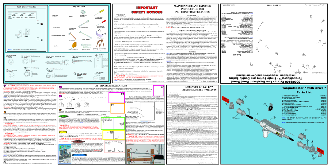
| TorqueMaster™ with idrive™ |
| ||||
|
|
|
|
| Parts List |
|
|
| ||
| t |
|
|
| (J) TORQUEMASTER TUBE |
|
|
| 1 ASSEMBLY |
|
|
|
|
| (K) CABLE /DRUM ASM. (PAIR) |
|
| # 280086 |
| ||
|
|
|
|
|
|
|
| |||
|
|
|
|
| (L) END BRACKET (LH) |
|
|
| # 282937 |
|
|
|
|
|
| (M) END BRACKET (RH) |
|
|
| # 282340 |
|
|
|
|
|
| (N) LOOSE WINDING SHAFT (SINGLE SPRING) |
| # 280066 |
| ||
| L | S |
|
| (O) COUNTER GEAR |
|
|
| # 284035 |
|
|
|
| (P) COUNTER COVER ASM. (RH) |
|
| # 287722 |
| |||
|
|
|
|
|
|
|
| |||
|
|
|
|
| COUNTER COVER ASM. (LH) (DOUBLE SPRING) | # 287721 |
| |||
|
|
|
|
| (Q) 36 TOOTH WORM GEAR |
|
|
| # 282335 |
|
| N |
|
|
| (R) idrive™ OPERATOR |
|
|
| SOLD SEPARATELY |
|
|
|
|
|
| (S) CENTER BRACKET ASM. |
|
|
| # 296246 |
|
|
|
|
|
| (T) LEFT DRUM WRAP |
|
|
| # 300550 |
|
| J |
|
|
| (U) RIGHT DRUM WRAP |
|
|
| # 300551 |
|
|
|
|
|
| (v) Low Headroom Kit |
|
|
| # 302879 |
|
| K |
|
| R | NOTE: See idrive™ Main Installation and Owners Manual for |
| ||||
|
|
|
|
| ||||||
|
|
|
|
| idrive™ parts |
|
|
|
|
|
|
|
|
|
| NOTE: Single Spring TorqueMaster™ shown in illustration. |
| ||||
U
Q
M
O
P