CENTER BEARING BRACKET | 13 |
|
HORIZONTAL PENCIL LINE | 5/16” x 1-5/8” |
LAG SCREW |
| SPRING WARNING |
| LABEL |
| VERTICAL PENCIL LINE | TAMPER-PROOF LAG SCREW |
| (CENTERLINE OF THE DOOR) |
| 5/16” x 2” OR 5/16 x 1-5/8” - |
| |
| | SPRING PAD OVER MASONRY |
Locate the center of the door and mark a vertical pencil line on the spring pad. Then measure the distance from the center of the mounting hole in the end bearing bracket to the top of the door. Using that same distance, mark a horizon- tal line on the spring pad, measuring up from the top of the door. Position the center bearing bracket along the vertical pencil line on the spring pad as shown. In addition, position the center bearing bracket halfway over the horizontal pencil line. This will level the torsion tube through the end bearing brackets when installed. Attach the center bearing bracket to the spring pad using (2) 5/16” x 1- 5/8” lag screws and (1) 5/16” x 2” tamper-proof lag screw.
IMPORTANT! Use the 5/16” x 1-5/8” tamper-proof lag screw ONLY if spring pad is mounted over masonry.
IMPORTANT! Tamper-proof lag screw MUST be attached through the bottom hole of the center bearing bracket.
| NYLON CENTER | RIGHT CABLE |
| DRUM (BLACK) |
| BUSHING |
| |
WINDING CONE
LEFT HAND WOUND BLACK WINDING CONE RIGHT HAND SIDE
14 | | RIGHT HAND WOUND |
SET SCREW | RED WINDING CONE |
| LEFT HAND SIDE |
Facing the inside of the door, lay the torsion tube on the floor. Lay the black color coded winding cone with spring and cable drum on the floor at the right end of the tube. Then lay the red color coded winding cone with spring and cable drum on the floor at the left end of the tube.
NOTE: Right and left hand is always determined from inside the building looking out.
NOTE: Some lighter weight doors are provided with only (1) torsion spring. Identify the spring(s) provided as either right hand wound (red winding cone), which goes on the LEFT HAND SIDE or left hand wound (black winding cone), which goes on the RIGHT HAND SIDE.
NOTE: The set screws used on all Torsion Counterbalance cable drums and winding cones are now painted red. DO NOT identify right and left hand side by the set screws.
Slide the nylon center bushing onto the torsion tube followed by the spring(s) and cable drums. The nylon center bushing, spring(s), and cable drums must be positioned as shown in the illustrations. With assistance, pick up the torsion tube assembly and slide the other end the of tube through one end bearing bracket. Lay the torsion tube into the center bearing bracket and slide the loose end of the tube into the opposite end bearing bracket. Position the torsion tube so that equal amounts of the tube extend from each end bearing bracket.
CENTER BEARING BRACKET | |
SPRING WITH RED COLOR | (2) 3/8-16 x 1-1/4” BOLT 15 |
CODED WINDING CONE: | | |
RIGHT HAND WOUND | | |
(MOUNTS ON LEFT SIDE) | | |
| | TORSION |
| | TUBE |
(2) 3/8-16 NUT STATIONARY | | SPRING |
NYLON CENTER | WARNING |
SPRING CONE | BUSHING | LABEL |
Slide the nylon center bushing into the end of (1) stationary spring cone and align the cone(s) with the holes in the center bearing bracket. Secure the spring(s) to the center bearing bracket with (2) 3/8-16 x 1-1/4” bolts and nuts.
IMPORTANT! Springs under tension can be dangerous. Spring warning tag must be attached to center bearing bracket in obvious sight. If this tag is missing, contact Wayne-Dalton Corp. for free replacements.
Clamp locking pliers onto both vertical tracks just above the third roller. This is to prevent door from raising while winding the spring(s).
WARNING!
FAILURE TO CLAMP TRACK CAN ALLOW DOOR TO RAISE AND CAUSE SEVERE INJURY OR DEATH.
| | COUNTERBALANCE | RED CABLE DRUM |
| | CABLE |
| | LEFT HAND SIDE |
| | |
| TORSION | | | |
| TUBE | 90° BEND | |
| | |
| CRIMPED CABLE | LOOSE CABLE | |
| BUTTON | 16 |
| BUTTON |
| | |
| | | |
Thread the counterbalance cables behind the rollers and around the back side of the cable drums. Before hooking the counterbalance cables into the cable drums, slide the loose cable buttons against the crimped buttons and with a pair of pliers, bend a 90 degree angle in the counterbalance cable.
Hook the counterbalance cables into the cable drums. Slide the left hand cable drum against the left hand end bearing bracket and tighten the set screws in the cable drum. Rotate the left hand cable drum until the counterbalance cable is taut. CABLE ENDS MUST WRAP DRUM 1/2 TO 3/4 TURN. Clamp locking pliers to the torsion tube and brace it against the jamb to hold the counterbalance cable taut.
Slide the right hand cable drum against the right hand end bearing bracket and rotate the cable drum until the counterbalance cable is taut. Tighten the set screws in the cable drum.
IMPORTANT! Tighten set screws one (1) full turn after making contact with the torsion tube. Counterbalance cable tension MUST be equal for both sides.
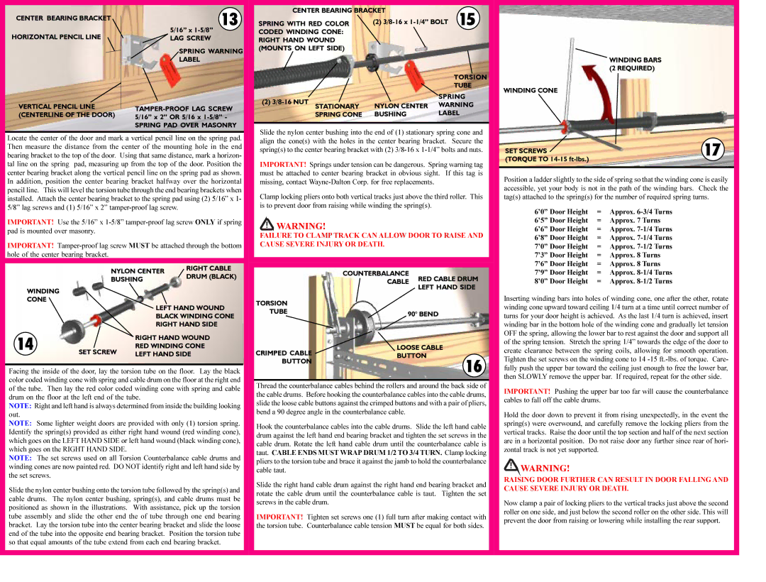
WINDING BARS (2 REQUIRED)
WINDING CONE
SET SCREWS | 17 |
|
(TORQUE TO 14-15 ft-lbs.) | |
Position a ladder slightly to the side of spring so that the winding cone is easily accessible, yet your body is not in the path of the winding bars. Check the tag(s) attached to the spring(s) for the number of required spring turns.
6’0” Door Height | = | Approx. 6-3/4 Turns |
6’5” Door Height | = | Approx. 7 Turns |
6’6” Door Height | = | Approx. 7-1/4 Turns |
6’8” Door Height | = | Approx. 7-1/4 Turns |
7’0” Door Height | = | Approx. 7-1/2 Turns |
7’3” Door Height | = | Approx. 8 Turns |
7’6” Door Height | = | Approx. 8 Turns |
7’9” Door Height | = | Approx. 8-1/4 Turns |
8’0” Door Height | = | Approx. 8-1/2 Turns |
Inserting winding bars into holes of winding cone, one after the other, rotate winding cone upward toward ceiling 1/4 turn at a time until correct number of turns for your door height is achieved. As the last 1/4 turn is achieved, insert winding bar in the bottom hole of the winding cone and gradually let tension OFF the spring, allowing the lower bar to rest against the door and support all of the spring tension. Stretch the spring 1/4” towards the edge of the door to create clearance between the spring coils, allowing for smooth operation. Tighten the set screws on the winding cone to 14 -15 ft.-lbs. of torque. Care- fully push the upper bar toward the ceiling just enough to free the lower bar, then SLOWLY remove the upper bar. If required, repeat for the other side.
IMPORTANT! Pushing the upper bar too far will cause the counterbalance cables to fall off the cable drums.
Hold the door down to prevent it from rising unexpectedly, in the event the spring(s) were overwound, and carefully remove the locking pliers from the vertical tracks. Raise the door until the top section and half of the next section are in a horizontal position. Do not raise door any further since rear of hori- zontal track is not yet supported.
 WARNING!
RAISING DOOR FURTHER CAN RESULT IN DOOR FALLING AND CAUSE SEVERE INJURY OR DEATH.
Now clamp a pair of locking pliers to the vertical tracks just above the second roller on one side, and just below the second roller on the other side. This will prevent the door from raising or lowering while installing the rear support.