ASSEMBLY
![]() WARNING: Stop the unit and dis- connect from the power source before opening the inlet cover or attempting to in- sert or remove the inlet restrictor, blower tube, nozzle, or vacuum tubes. The motor must be stopped and the impeller blades no longer turning to avoid serious injury from the rotating blades.
WARNING: Stop the unit and dis- connect from the power source before opening the inlet cover or attempting to in- sert or remove the inlet restrictor, blower tube, nozzle, or vacuum tubes. The motor must be stopped and the impeller blades no longer turning to avoid serious injury from the rotating blades.
![]() WARNING: If you receive your unit assembled, check each step to in- sure your unit is properly assembled and all fasteners are secure. Follow all safety information in the manual and on unit.
WARNING: If you receive your unit assembled, check each step to in- sure your unit is properly assembled and all fasteners are secure. Follow all safety information in the manual and on unit.
S A standard screwdriver is required for assembly.
BLOWER ASSEMBLY
NOTE: Assembly intructions for using your unit as a vacuum follow this section.
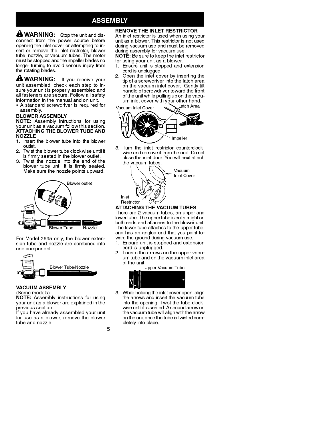
ATTACHING THE BLOWER TUBE AND NOZZLE
1.Insert the blower tube into the blower outlet.
2.Twist the blower tube clockwise until it is firmly seated in the blower outlet.
3.Twist the nozzle into the end of the blower tube until it is firmly seated. Make sure the nozzle points upward.
Blower outlet
Blower Tube | Nozzle |
For Model 2695 only, the blower exten- sion tube and nozzle are combined into one component.
Blower Tube/Nozzle
VACUUM ASSEMBLY (Some models)
NOTE: Assembly instructions for using your unit as a blower are explained in the previous section.
If you have already assembled your unit for use as a blower, remove the blower tube and nozzle.
5
REMOVE THE INLET RESTRICTOR
An inlet restrictor is used when using your unit as a blower. This restrictor is not used during vacuum use and must be removed during assembly for vacuum use.
NOTE: Be sure to keep the inlet restrictor for using your unit as a blower.
1.Ensure unit is stopped and extension cord is unplugged.
2.Open the inlet cover by inserting the tip of a screwdriver into the latch area on the vacuum inlet cover. Gently tilt handle of screwdriver toward the front of the unit while pulling up on the vacu- um inlet cover with your other hand.
Vacuum Inlet Cover | Latch Area |
|
![]() Impeller
Impeller
3.Turn the inlet restrictor counterclock- wise and remove it from the unit. Do not close the inlet door. You will next attach the vacuum tubes.
Vacuum
![]() Inlet Cover
Inlet Cover
Inlet
Restrictor
ATTACHING THE VACUUM TUBES There are 2 vacuum tubes, an upper and lower tube. The upper tube is cut straight on both ends and attaches to the blower unit. The lower tube attaches to the upper tube, and has an angled end that you point to- ward the ground during vacuum use.
1.Ensure unit is stopped and extension cord is unplugged.
2.Locate the arrows on the upper vacu- um tube and on the vacuum inlet area of the unit.
Upper Vacuum Tube
3.While holding the inlet cover open, align the arrows and insert the vacuum tube into the opening. Twist the tube clock- wise until it is seated. A second arrow on the vacuum tube will align with the arrow on the unit once the tube is twisted com- pletely into place.