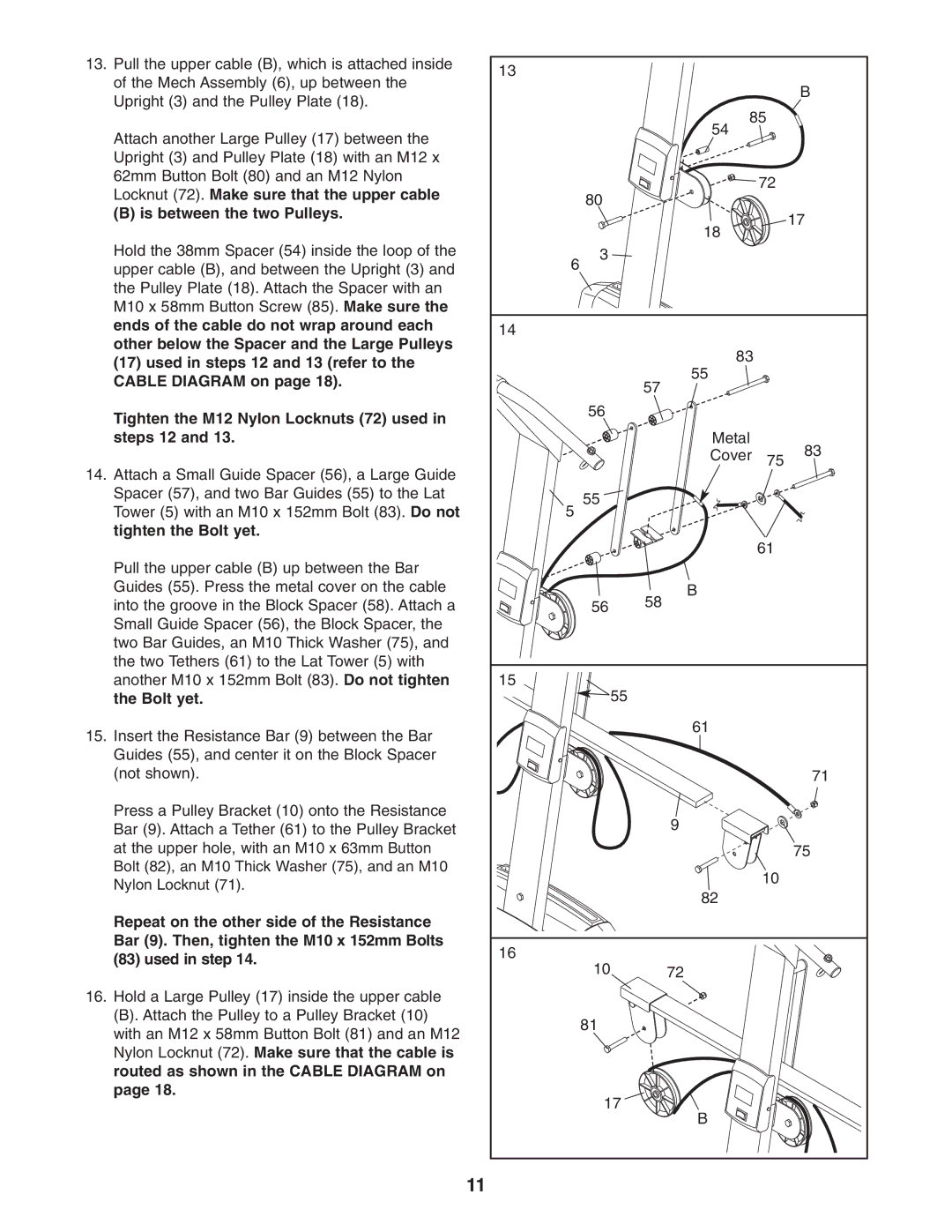
13. Pull the upper cable (B), which is attached inside | 13 |
|
|
|
of the Mech Assembly (6), up between the |
|
|
| |
|
|
| B | |
Upright (3) and the Pulley Plate (18). |
|
|
| |
| 85 |
| ||
|
|
| ||
Attach another Large Pulley (17) between the |
| 54 |
|
|
|
|
|
| |
Upright (3) and Pulley Plate (18) with an M12 x |
|
|
|
|
62mm Button Bolt (80) and an M12 Nylon |
|
| 72 |
|
Locknut (72). Make sure that the upper cable | 80 |
|
| |
|
|
| ||
(B) is between the two Pulleys. |
|
|
| |
|
|
| 17 | |
|
| 18 |
| |
|
|
|
| |
Hold the 38mm Spacer (54) inside the loop of the | 3 |
|
|
|
upper cable (B), and between the Upright (3) and | 6 |
|
|
|
|
|
|
| |
the Pulley Plate (18). Attach the Spacer with an |
|
|
|
|
M10 x 58mm Button Screw (85). Make sure the |
|
|
|
|
ends of the cable do not wrap around each | 14 |
|
|
|
other below the Spacer and the Large Pulleys |
|
|
| |
| 83 |
|
| |
(17) used in steps 12 and 13 (refer to the |
|
|
| |
| 55 |
|
| |
CABLE DIAGRAM on page 18). |
|
|
| |
| 57 |
|
| |
|
|
|
| |
Tighten the M12 Nylon Locknuts (72) used in | 56 |
|
|
|
|
|
|
| |
steps 12 and 13. |
| Metal |
| 83 |
|
| Cover | 75 | |
14. Attach a Small Guide Spacer (56), a Large Guide |
|
| ||
|
|
|
| |
Spacer (57), and two Bar Guides (55) to the Lat | 55 |
|
|
|
Tower (5) with an M10 x 152mm Bolt (83). Do not |
|
|
| |
5 |
|
|
| |
tighten the Bolt yet. |
|
| 61 |
|
|
|
|
| |
Pull the upper cable (B) up between the Bar |
|
|
|
|
Guides (55). Press the metal cover on the cable |
| B |
|
|
into the groove in the Block Spacer (58). Attach a | 56 | 58 |
|
|
Small Guide Spacer (56), the Block Spacer, the |
|
|
|
|
two Bar Guides, an M10 Thick Washer (75), and |
|
|
|
|
the two Tethers (61) to the Lat Tower (5) with |
|
|
|
|
another M10 x 152mm Bolt (83). Do not tighten | 15 |
|
|
|
the Bolt yet. | 55 |
|
|
|
15. Insert the Resistance Bar (9) between the Bar |
| 61 |
|
|
|
|
|
| |
Guides (55), and center it on the Block Spacer |
|
|
|
|
(not shown). |
|
|
| 71 |
Press a Pulley Bracket (10) onto the Resistance |
| 9 |
|
|
Bar (9). Attach a Tether (61) to the Pulley Bracket |
|
|
| |
at the upper hole, with an M10 x 63mm Button |
|
|
| 75 |
Bolt (82), an M10 Thick Washer (75), and an M10 |
|
| 10 |
|
Nylon Locknut (71). |
|
|
| |
| 82 |
|
| |
|
|
|
| |
Repeat on the other side of the Resistance |
|
|
|
|
Bar (9). Then, tighten the M10 x 152mm Bolts | 16 |
|
|
|
(83) used in step 14. |
|
|
| |
10 | 72 |
|
| |
|
|
| ||
16. Hold a Large Pulley (17) inside the upper cable |
|
|
|
|
(B). Attach the Pulley to a Pulley Bracket (10) | 81 |
|
|
|
with an M12 x 58mm Button Bolt (81) and an M12 |
|
|
| |
|
|
|
| |
Nylon Locknut (72). Make sure that the cable is |
|
|
|
|
routed as shown in the CABLE DIAGRAM on |
|
|
|
|
page 18. | 17 |
|
|
|
| B |
|
| |
|
|
|
| |
11