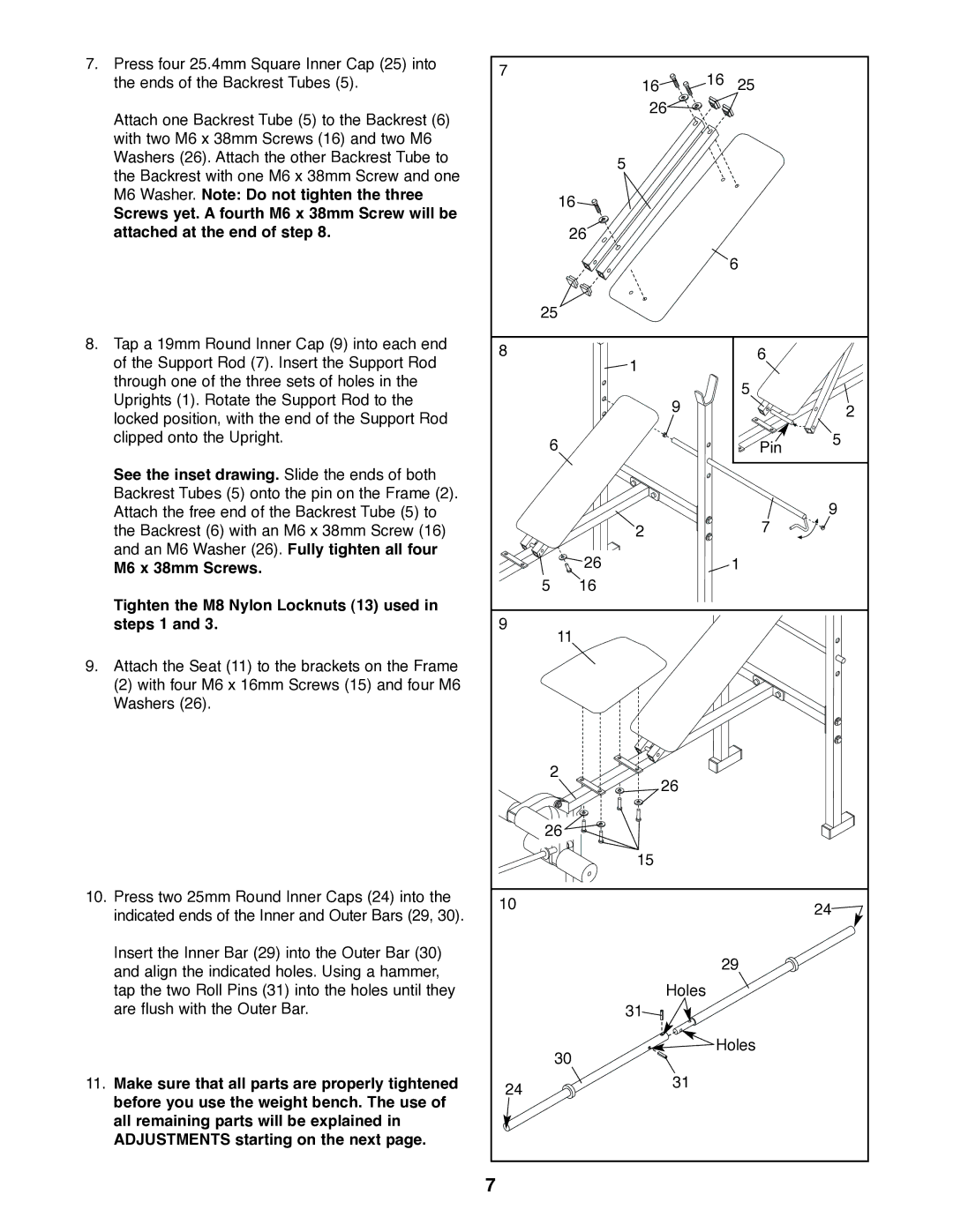
7. | Press four 25.4mm Square Inner Cap (25) into | 7 |
| 16 |
|
|
| the ends of the Backrest Tubes (5). | 16 | 25 |
| ||
|
|
| ||||
| Attach one Backrest Tube (5) to the Backrest (6) |
| 26 |
|
|
|
|
|
|
|
|
| |
| with two M6 x 38mm Screws (16) and two M6 |
|
|
|
|
|
| Washers (26). Attach the other Backrest Tube to |
| 5 |
|
|
|
| the Backrest with one M6 x 38mm Screw and one |
|
|
|
| |
|
|
|
|
|
| |
| M6 Washer. Note: Do not tighten the three | 16 |
|
|
| |
| Screws yet. A fourth M6 x 38mm Screw will be |
|
|
| ||
|
|
|
|
|
| |
| attached at the end of step 8. |
| 26 |
|
|
|
|
|
|
|
| 6 |
|
|
| 25 |
|
|
|
|
8. | Tap a 19mm Round Inner Cap (9) into each end | 8 |
|
| 6 |
|
| of the Support Rod (7). Insert the Support Rod | 1 |
|
| ||
|
|
|
|
| ||
| through one of the three sets of holes in the |
|
|
| 5 |
|
| Uprights (1). Rotate the Support Rod to the |
|
|
|
| |
|
| 9 |
|
| 2 | |
| locked position, with the end of the Support Rod |
|
|
| ||
|
|
|
|
| ||
|
|
|
|
|
| |
| clipped onto the Upright. | 6 |
|
| Pin | 5 |
|
|
|
|
| ||
| See the inset drawing. Slide the ends of both |
|
|
|
|
|
| Backrest Tubes (5) onto the pin on the Frame (2). |
|
|
|
| 9 |
| Attach the free end of the Backrest Tube (5) to |
|
|
| 7 | |
| the Backrest (6) with an M6 x 38mm Screw (16) |
| 2 |
|
| |
| and an M6 Washer (26). Fully tighten all four |
| 26 |
| 1 |
|
| M6 x 38mm Screws. |
|
|
| ||
|
| 5 | 16 |
|
|
|
| Tighten the M8 Nylon Locknuts (13) used in |
|
|
|
|
|
| steps 1 and 3. | 9 |
|
|
|
|
|
| 11 |
|
|
| |
9. | Attach the Seat (11) to the brackets on the Frame |
|
|
|
|
|
| (2) with four M6 x 16mm Screws (15) and four M6 |
|
|
|
|
|
| Washers (26). |
|
|
|
|
|
|
| 2 | 26 |
|
|
|
|
|
|
|
|
| |
|
| 26 |
|
|
|
|
|
|
| 15 |
|
|
|
10. | Press two 25mm Round Inner Caps (24) into the | 10 |
|
|
| 24 |
| indicated ends of the Inner and Outer Bars (29, 30). |
|
|
| ||
|
|
|
|
| ||
|
|
|
|
|
| |
| Insert the Inner Bar (29) into the Outer Bar (30) |
|
| 29 |
| |
| and align the indicated holes. Using a hammer, |
|
|
| ||
|
|
|
|
|
| |
| tap the two Roll Pins (31) into the holes until they |
| Holes |
|
|
|
| are flush with the Outer Bar. |
| 31 |
|
|
|
|
| 30 | Holes |
| ||
|
|
|
|
| ||
11. | Make sure that all parts are properly tightened | 24 | 31 |
|
|
|
| before you use the weight bench. The use of |
|
|
|
| |
|
|
|
|
|
| |
| all remaining parts will be explained in |
|
|
|
|
|
| ADJUSTMENTS starting on the next page. |
|
|
|
|
|
|
| 7 |
|
|
|
|