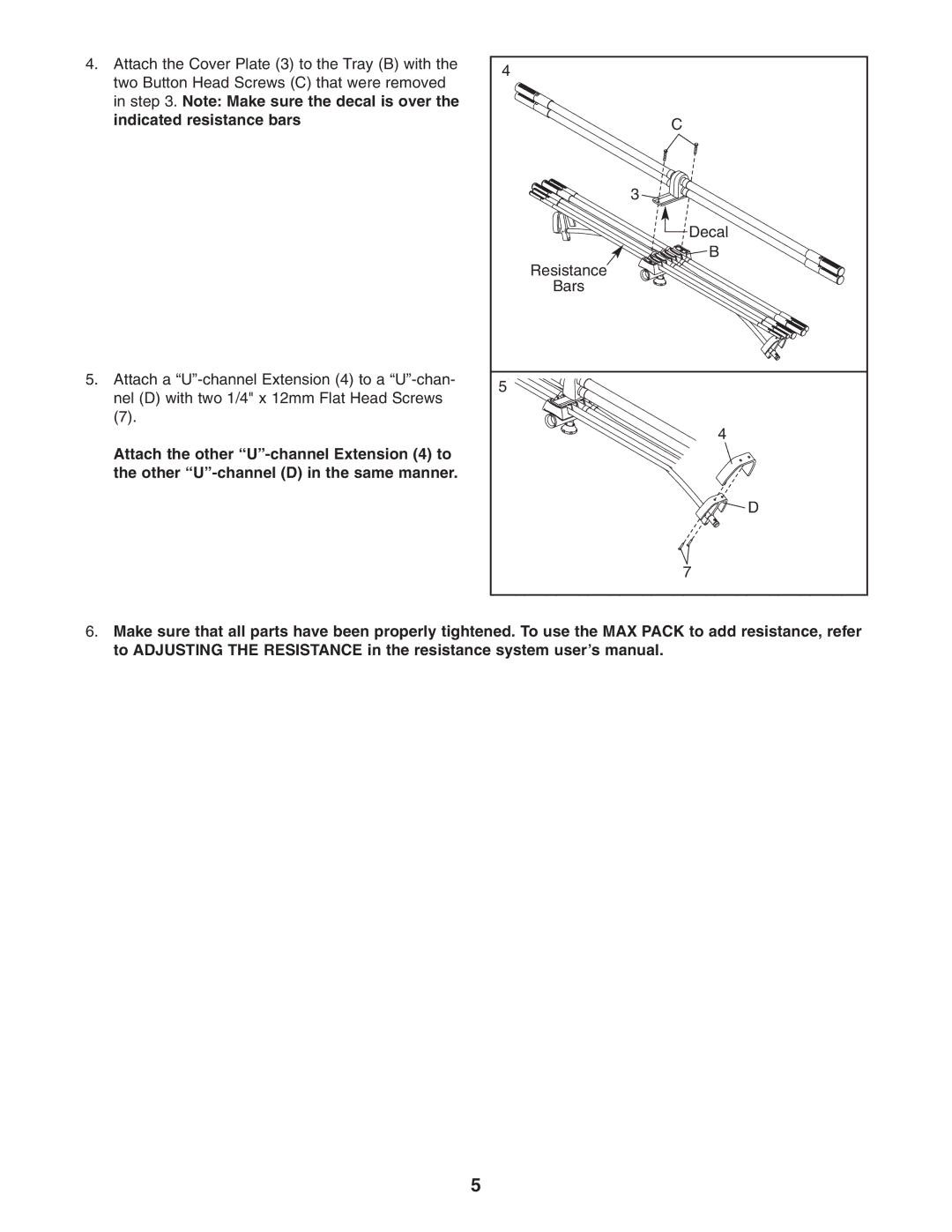
4.Attach the Cover Plate (3) to the Tray (B) with the two Button Head Screws (C) that were removed in step 3. Note: Make sure the decal is over the indicated resistance bars
5.Attach a
(7).
Attach the other
4 |
C |
3 |
Decal |
B |
Resistance |
Bars |
5 |
4 |
D |
7 |
6.Make sure that all parts have been properly tightened. To use the MAX PACK to add resistance, refer to ADJUSTING THE RESISTANCE in the resistance system user’s manual.
5