Burner Specification & Data sheet — Riello Gas/Oil Burners
Burner specifications and settings (continued)
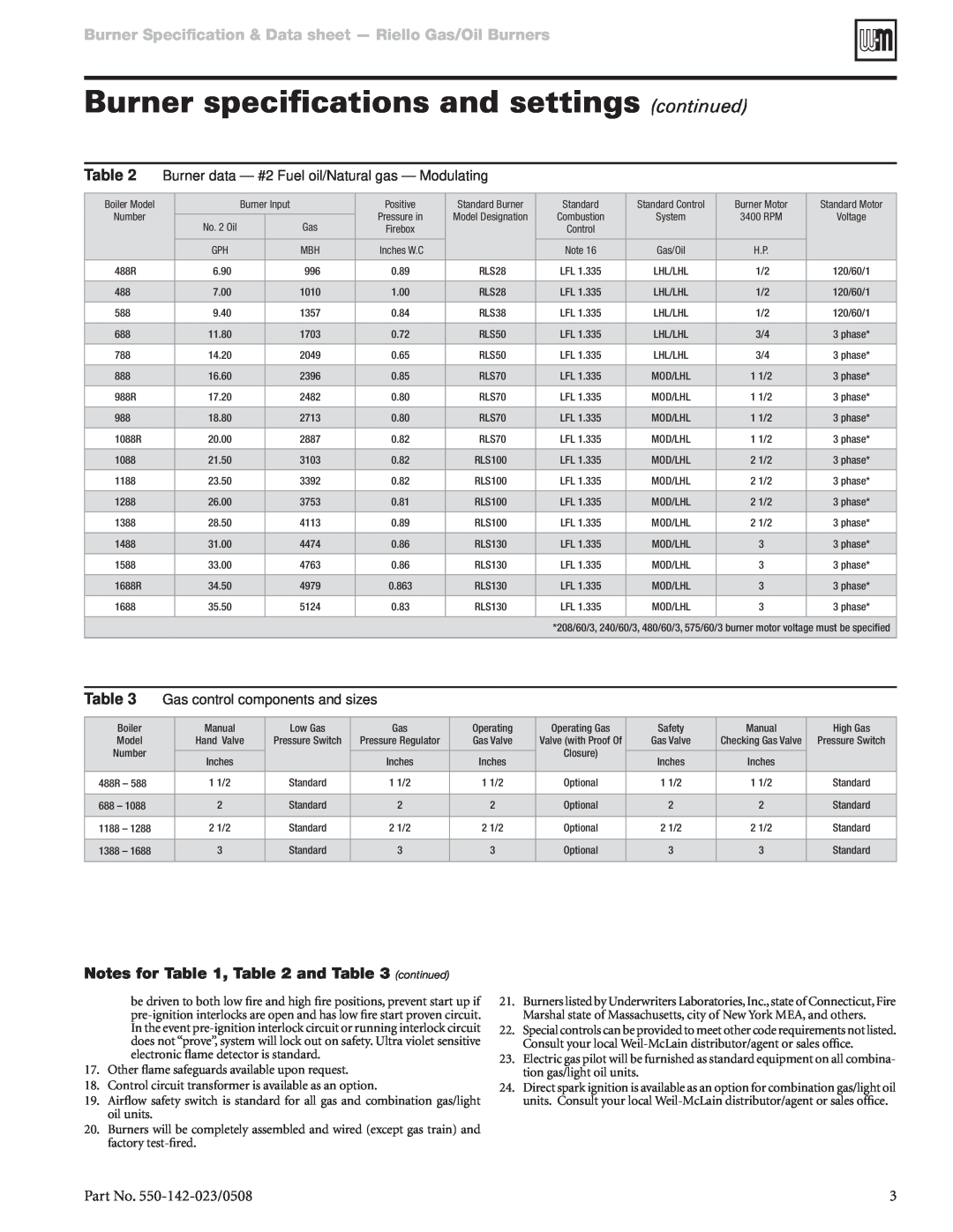
Table 2 | Burner data — #2 Fuel oil/Natural gas — Modulating |
|
|
|
| |||||
|
|
|
|
|
|
|
|
|
|
|
Boiler Model |
|
| Burner Input | Positive | Standard Burner | Standard | Standard Control | Burner Motor | Standard Motor | |
Number |
|
|
|
| Pressure in | Model Designation | Combustion | System | 3400 RPM | Voltage |
| No. 2 Oil |
| Gas | |||||||
|
|
| Firebox |
| Control |
|
|
| ||
|
|
|
|
|
|
|
|
|
|
|
|
| GPH |
| MBH | Inches W.C |
| Note 16 | Gas/Oil | H.P. |
|
|
|
|
|
|
|
|
|
|
|
|
488R |
| 6.90 |
| 996 | 0.89 | RLS28 | LFL 1.335 | LHL/LHL | 1/2 | 120/60/1 |
|
|
|
|
|
|
|
|
|
|
|
488 |
| 7.00 |
| 1010 | 1.00 | RLS28 | LFL 1.335 | LHL/LHL | 1/2 | 120/60/1 |
|
|
|
|
|
|
|
|
|
|
|
588 |
| 9.40 |
| 1357 | 0.84 | RLS38 | LFL 1.335 | LHL/LHL | 1/2 | 120/60/1 |
|
|
|
|
|
|
|
|
|
|
|
688 |
| 11.80 |
| 1703 | 0.72 | RLS50 | LFL 1.335 | LHL/LHL | 3/4 | 3 phase* |
|
|
|
|
|
|
|
|
|
|
|
788 |
| 14.20 |
| 2049 | 0.65 | RLS50 | LFL 1.335 | LHL/LHL | 3/4 | 3 phase* |
|
|
|
|
|
|
|
|
|
|
|
888 |
| 16.60 |
| 2396 | 0.85 | RLS70 | LFL 1.335 | MOD/LHL | 1 1/2 | 3 phase* |
|
|
|
|
|
|
|
|
|
|
|
988R |
| 17.20 |
| 2482 | 0.80 | RLS70 | LFL 1.335 | MOD/LHL | 1 1/2 | 3 phase* |
|
|
|
|
|
|
|
|
|
|
|
988 |
| 18.80 |
| 2713 | 0.80 | RLS70 | LFL 1.335 | MOD/LHL | 1 1/2 | 3 phase* |
|
|
|
|
|
|
|
|
|
|
|
1088R |
| 20.00 |
| 2887 | 0.82 | RLS70 | LFL 1.335 | MOD/LHL | 1 1/2 | 3 phase* |
|
|
|
|
|
|
|
|
|
|
|
1088 |
| 21.50 |
| 3103 | 0.82 | RLS100 | LFL 1.335 | MOD/LHL | 2 1/2 | 3 phase* |
|
|
|
|
|
|
|
|
|
|
|
1188 |
| 23.50 |
| 3392 | 0.82 | RLS100 | LFL 1.335 | MOD/LHL | 2 1/2 | 3 phase* |
|
|
|
|
|
|
|
|
|
|
|
1288 |
| 26.00 |
| 3753 | 0.81 | RLS100 | LFL 1.335 | MOD/LHL | 2 1/2 | 3 phase* |
|
|
|
|
|
|
|
|
|
|
|
1388 |
| 28.50 |
| 4113 | 0.89 | RLS100 | LFL 1.335 | MOD/LHL | 2 1/2 | 3 phase* |
|
|
|
|
|
|
|
|
|
|
|
1488 |
| 31.00 |
| 4474 | 0.86 | RLS130 | LFL 1.335 | MOD/LHL | 3 | 3 phase* |
|
|
|
|
|
|
|
|
|
|
|
1588 |
| 33.00 |
| 4763 | 0.86 | RLS130 | LFL 1.335 | MOD/LHL | 3 | 3 phase* |
|
|
|
|
|
|
|
|
|
|
|
1688R |
| 34.50 |
| 4979 | 0.863 | RLS130 | LFL 1.335 | MOD/LHL | 3 | 3 phase* |
|
|
|
|
|
|
|
|
|
|
|
1688 |
| 35.50 |
| 5124 | 0.83 | RLS130 | LFL 1.335 | MOD/LHL | 3 | 3 phase* |
|
|
|
|
|
|
|
|
|
|
|
|
|
|
|
|
|
| *208/60/3, 240/60/3, 480/60/3, 575/60/3 burner motor voltage must be specified | |||
|
|
|
|
|
|
|
|
|
|
|
Table 3 | Gas control components and sizes |
|
|
|
|
| |||
|
|
|
|
|
|
|
|
|
|
Boiler |
| Manual | Low Gas | Gas | Operating | Operating Gas | Safety | Manual | High Gas |
Model |
| Hand Valve | Pressure Switch | Pressure Regulator | Gas Valve | Valve (with Proof Of | Gas Valve | Checking Gas Valve | Pressure Switch |
Number |
|
|
|
|
| Closure) |
|
|
|
| Inches |
| Inches | Inches | Inches | Inches |
| ||
|
|
|
|
| |||||
|
|
|
|
|
|
|
|
|
|
488R – 588 |
| 1 1/2 | Standard | 1 1/2 | 1 1/2 | Optional | 1 1/2 | 1 1/2 | Standard |
|
|
|
|
|
|
|
|
|
|
688 – 1088 |
| 2 | Standard | 2 | 2 | Optional | 2 | 2 | Standard |
|
|
|
|
|
|
|
|
|
|
1188 – 1288 |
| 2 1/2 | Standard | 2 1/2 | 2 1/2 | Optional | 2 1/2 | 2 1/2 | Standard |
|
|
|
|
|
|
|
|
|
|
1388 – 1688 |
| 3 | Standard | 3 | 3 | Optional | 3 | 3 | Standard |
|
|
|
|
|
|
|
|
|
|
Notes for Table 1, Table 2 and Table 3 (continued)
be driven to both low fire and high fire positions, prevent start up if
17.Other flame safeguards available upon request.
18.Control circuit transformer is available as an option.
19.Airflow safety switch is standard for all gas and combination gas/light oil units.
20.Burners will be completely assembled and wired (except gas train) and factory
21.Burners listed by Underwriters Laboratories, Inc., state of Connecticut, Fire Marshal state of Massachusetts, city of New York MEA, and others.
22.Special controls can be provided to meet other code requirements not listed. Consult your local
23.Electric gas pilot will be furnished as standard equipment on all combina- tion gas/light oil units.
24.Direct spark ignition is available as an option for combination gas/light oil units. Consult your local
Part No. | 3 |