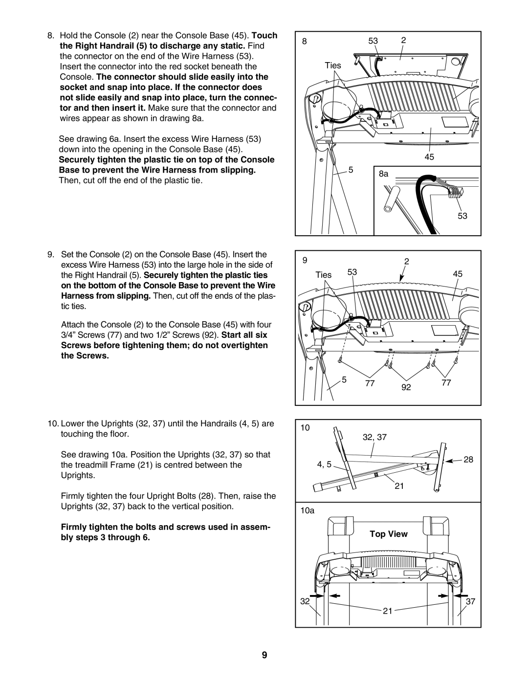
8.Hold the Console (2) near the Console Base (45). Touch the Right Handrail (5) to discharge any static. Find the connector on the end of the Wire Harness (53). Insert the connector into the red socket beneath the Console. The connector should slide easily into the socket and snap into place. If the connector does not slide easily and snap into place, turn the connec- tor and then insert it. Make sure that the connector and wires appear as shown in drawing 8a.
See drawing 6a. Insert the excess Wire Harness (53) down into the opening in the Console Base (45).
Securely tighten the plastic tie on top of the Console Base to prevent the Wire Harness from slipping. Then, cut off the end of the plastic tie.
9.Set the Console (2) on the Console Base (45). Insert the excess Wire Harness (53) into the large hole in the side of the Right Handrail (5). Securely tighten the plastic ties on the bottom of the Console Base to prevent the Wire Harness from slipping. Then, cut off the ends of the plas- tic ties.
Attach the Console (2) to the Console Base (45) with four 3/4” Screws (77) and two 1/2” Screws (92). Start all six
Screws before tightening them; do not overtighten the Screws.
10.Lower the Uprights (32, 37) until the Handrails (4, 5) are touching the floor.
See drawing 10a. Position the Uprights (32, 37) so that the treadmill Frame (21) is centred between the Uprights.
Firmly tighten the four Upright Bolts (28). Then, raise the Uprights (32, 37) back to the vertical position.
Firmly tighten the bolts and screws used in assem- bly steps 3 through 6.
8 |
|
| 53 | 2 |
|
Ties |
|
|
|
|
|
|
|
|
|
| 45 |
|
| 5 | 8a |
|
|
|
|
|
|
| |
|
|
|
|
| 53 |
9 |
|
|
| 2 |
|
Ties |
| 53 |
|
| 45 |
| 5 |
| 77 | 92 | 77 |
|
|
| |||
|
|
|
|
| |
10 |
|
| 32, 37 |
|
|
|
|
|
|
|
4, 5 | 28 |
| |
| 21 |
10a
Top View
32 | 37 |
21
9