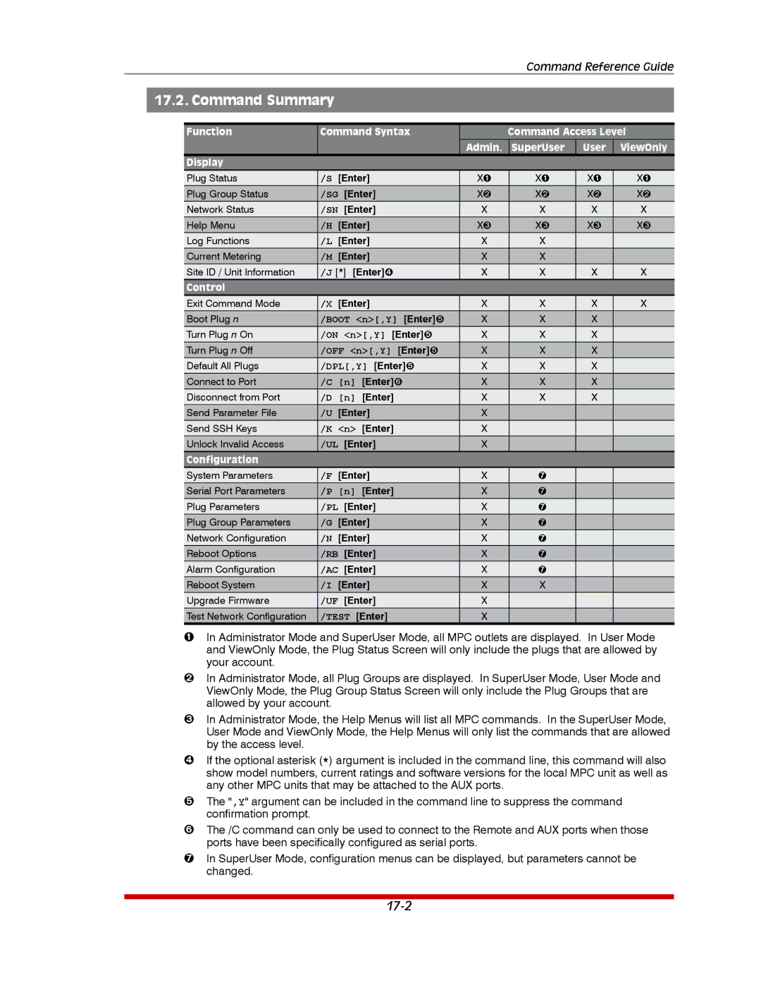
MPC-18H-2, MPC-20V-2, MPC-20VS32-3, MPC-20VD32-3, MPC-16H-2 specifications
The Western Telematic MPC series is renowned for its robust and versatile remote power management solutions. Among its offerings, the MPC-20VS16-3, MPC-20VD16-3, MPC-20VD20-2, MPC-20VS20-1, and MPC-20VS20-2 stand out as exceptional products tailored to meet the demands of modern telecommunications and data center environments.One of the key features across this series is the ability to monitor and control up to 20 power outlets, which allows for efficient resource management and reduces downtime. Each model in the series accommodates various configurations, including both switched and non-switched outlets. This flexibility makes it easier for operators to manage power distribution according to their specific needs.
The integration of real-time monitoring capabilities is another highlight of the MPC series. Users can track power consumption, voltage, and current for each outlet, enabling better decision-making to optimize energy usage. This feature contributes significantly to the overall efficiency of operations, ensuring that resources are utilized effectively.
Communication is seamless with the Western Telematic MPC series, as these models are equipped with multiple network connectivity options. They support both SNMP (Simple Network Management Protocol) and Telnet, facilitating easy integration with existing network management systems. Additionally, the devices can send alerts and notifications via email or SMS, keeping operators informed about any changes in power status or potential issues.
The MPC models are designed with redundancy and reliability in mind. They come equipped with advanced surge protection, ensuring sensitive equipment remains safe from power spikes. The rugged construction of the units ensures they can withstand the rigors of data center environments, with an emphasis on heat dissipation and airflow management.
Security features are also a priority. The MPC series includes user authentication and access control to prevent unauthorized users from manipulating power settings. The ability to set user permissions ensures that only designated personnel can operate sensitive components, enhancing operational security.
Energy efficiency is a guiding principle in the design of the MPC series. By providing tools for monitoring and controlling power usage, these devices contribute to a reduction in energy costs, aligning with sustainability goals sought by modern enterprises.
In conclusion, the Western Telematic MPC-20VS16-3, MPC-20VD16-3, MPC-20VD20-2, MPC-20VS20-1, and MPC-20VS20-2 are exemplary models in the field of remote power management. With features such as comprehensive outlet control, real-time monitoring, robust communication options, security protocols, and a focus on energy efficiency, these units are engineered to meet the rigorous demands of the telecommunications and data center sectors. By implementing these advanced technologies, operators can enhance their operational capabilities while also contributing to long-term sustainability.

