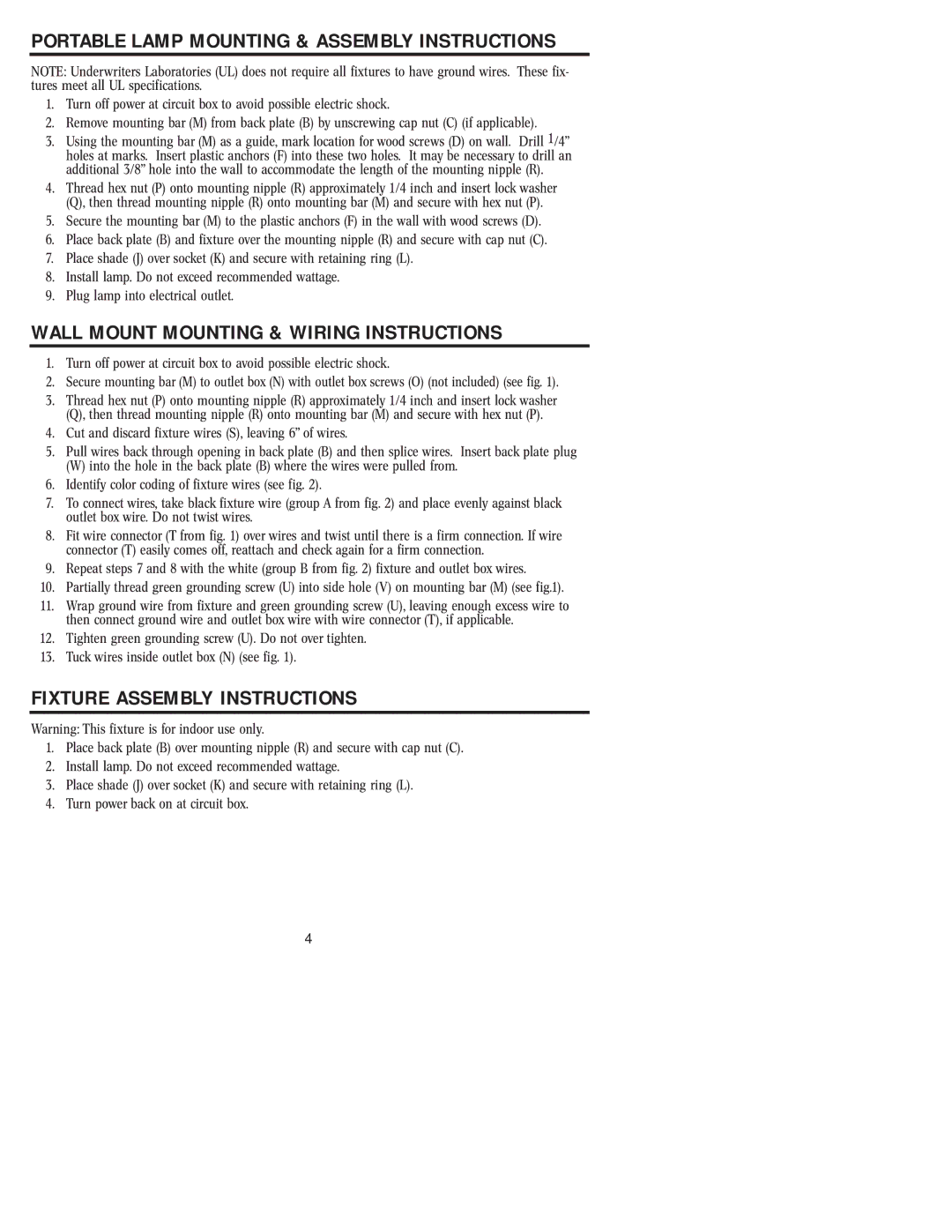
PORTABLE LAMP MOUNTING & ASSEMBLY INSTRUCTIONS

NOTE: Underwriters Laboratories (UL) does not require all fixtures to have ground wires. These fix- tures meet all UL specifications.

1.Turn off power at circuit box to avoid possible electric shock.

2.Remove mounting bar (M) from back plate (B) by unscrewing cap nut (C) (if applicable).

3.Using the mounting bar (M) as a guide, mark location for wood screws (D) on wall. Drill 1/4” holes at marks. Insert plastic anchors (F) into these two holes. It may be necessary to drill an additional 3/8” hole into the wall to accommodate the length of the mounting nipple (R).

4.Thread hex nut (P) onto mounting nipple (R) approximately 1/4 inch and insert lockwasher (Q), then thread mounting nipple (R) onto mounting bar (M) and secure with hex nut (P).

5.Secure the mounting bar (M) to the plastic anchors (F) in the wall with wood screws (D).

6.Place back plate (B) and fixture over the mounting nipple (R) and secure with cap nut (C).

7.Place shade (J) over socket (K) and secure with retaining ring (L).

8.Install lamp. Do not exceed recommended wattage.

9.Plug lamp into electrical outlet.

WALL MOUNT MOUNTING & WIRING INSTRUCTIONS

1.Turn off power at circuit box to avoid possible electric shock.

2.Secure mounting bar (M) to outlet box (N) with outlet box screws (O) (not included) (see fig. 1).

3.Thread hex nut (P) onto mounting nipple (R) approximately 1/4 inch and insert lockwasher (Q), then thread mounting nipple (R) onto mounting bar (M) and secure with hex nut (P).

4.Cut and discard fixture wires (S), leaving 6” of wires.

5.Pull wires back through opening in back plate (B) and then splice wires. Insert back plate plug

(W)into the hole in the back plate (B) where the wires were pulled from.

6.Identify color coding of fixture wires (see fig. 2).

7.To connect wires, take black fixture wire (group A from fig. 2) and place evenly against black outlet box wire. Do not twist wires.

8.Fit wire connector (T from fig. 1) over wires and twist until there is a firm connection. If wire connector (T) easily comes off, reattach and check again for a firm connection.

9.Repeat steps 7 and 8 with the white (group B from fig. 2) fixture and outlet box wires.

10.Partially thread green grounding screw (U) into side hole (V) on mounting bar (M) (see fig.1).

11.Wrap ground wire from fixture and green grounding screw (U), leaving enough excess wire to then connect ground wire and outlet box wire with wire connector (T), if applicable.

12.Tighten green grounding screw (U). Do not over tighten.

13.Tuckwires inside outlet box (N) (see fig. 1).

FIXTURE ASSEMBLY INSTRUCTIONS

Warning: This fixture is for indoor use only.

1.Place back plate (B) over mounting nipple (R) and secure with cap nut (C).

2.Install lamp. Do not exceed recommended wattage.

3.Place shade (J) over socket (K) and secure with retaining ring (L).

4.Turn power back on at circuit box.

4

Page 4
Image 4
Westinghouse W-231 owner manual Wall Mount Mounting & Wiring Instructions, Fixture Assembly Instructions

W-231 specifications

The Westinghouse W-231 is an innovative steam turbine generator designed primarily for utility and industrial applications. Known for its remarkable efficiency and reliability, the W-231 brings advanced technology and features that support a range of energy generation needs.

One of the main features of the W-231 is its exceptional thermal efficiency. The turbine is designed to operate in a variety of steam conditions, allowing it to effectively maximize energy extraction from steam through optimized blade design. This design not only enhances performance but also reduces fuel consumption, making it an environmentally friendly option for energy production.

The W-231 utilizes advanced materials and construction techniques to ensure durability and longevity. Its components are engineered to withstand high temperatures and pressures, resulting in reduced maintenance requirements and extended operational life. This resilience is crucial for power plants that operate under continuous stress and demand consistent performance.

Additionally, the W-231 incorporates state-of-the-art digital control systems, enhancing its operational flexibility and precision. These control systems allow for real-time monitoring and adjustments, ensuring optimal performance and responding proactively to any fluctuations in operational conditions. The integration of predictive maintenance technologies further minimizes downtime and enhances reliability.

The W-231 also boasts a compact design, which makes it suitable for various installation environments, including limited space applications. Its modular construction allows for easy scalability and adaptability, catering to both small-scale and large-scale power generation projects.

In terms of emissions control, the W-231 is designed to meet stringent environmental standards, contributing to a cleaner energy landscape. The turbine's efficiency helps to minimize the carbon footprint associated with electricity production, aligning with global efforts to transition toward sustainable energy sources.

Overall, the Westinghouse W-231 represents a significant advancement in steam turbine technology, combining efficiency, durability, and cutting-edge digital control features. Its ability to deliver reliable power while meeting environmental regulations positions it as a leading choice for utilities and industries looking to optimize their energy generation capabilities. As energy demands continue to grow, the W-231 stands out as a vital component in the quest for sustainable and reliable power solutions.