Three-wire installation (if a four-wire system is not available): The power supply cord must have three, No.-1 0 copper wires to match a three-wire receptacle of NEMA Type 1O-30R(see Figure 4).
Direct wire
The washer/dryer can be connected directly to fused disconnect or circuit breaker box with four-wire or three-wire flexible armored or non-metallic sheathed copper cable (with grounding wire). Do Not use two-wire with bare grounding wire. All current-carrying wires must be insulated.
A conduit connector must be installed at junction box. USEONLY lo-GAUGE SOLID COPPER WIRE. DO NOT USE ALUMINUM WIRE.Allow four feet of slack in the line so dryer can be moved if servicing is ever necessary.
Electrical! A’connection
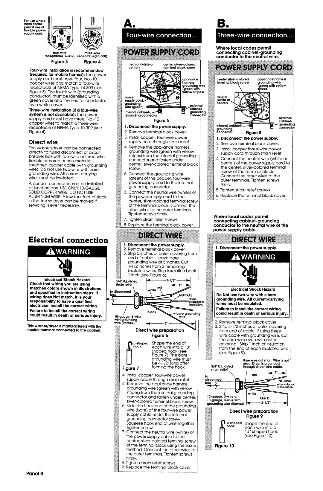
Figure 5
1. Disconnect the power supply.
2. Remove terminal block cover.
3. Install copper, four-wire power supply cord through strain relief.
4. Remove the appliance harness grounding wire (green with yellow stripes) from the internal grounding connector and fasten under center, silver-colored terminal block screw.
5. Connect the grounding wire (green) of the copper, four-wire power supply cord to the internal grounding connector.
6. Connect the neutral wire (white) of the power supply cord to the center, silver-colored terminal screw of the terminal block. Connect the other wires to the outer terminals. Tighten screws firmly.
7. Tighten strain relief screws.
8. Replace the terminal block cover.
J
.-.-.
.....
.....
,:,:.:
:.:,>
.....
,:,:,:
:;::)
22.
4
1.Disconnect the power supply.
2.Remove terminal block cover.
3.Install copper three-wire power supply cord through strain relief.
4.Connect the neutral wire (white or center) of the power supply cord to the center, silver-colored terminal screw of the terminal block.
Connect the other wires to the outer terminals. Tighten screws firmly.
5.Tighten strain relief screws.
6.Replace the terminal block cover.
Where local codes permit connecting cabinet- rounding conductor to the neu 3ral wire of the power supply cable:
m *-
Electrical Shock Hazard Check that wiring you are using matches colors shown in illustrations and specified in instruction steps. If wiring does Not match, it is your responsibility to have a qualified electrician install the correct wiring.
Failure to install the correct wiring could result in death or serious injury.
This washer/dryer Is manufactured wlth the neutral termlnal connected to the cabinet.
$$ | 1. Disconnect | the power | supply. | | . . . . :.- | | | | | | | |
| ..-.-.-.-.-...~ | | | power | supply. | |
$$ 2. Remove terminal block cover. | | $$$$j~1. Disconnect the | |
$3; 3. Strip 5 inches of outer covering from | | | | | | | | | | |
::::::::::: | | | | | | | | | | | | | | | | |
::::::::::: | end of cable. | Leave bare | | | | | | | | | | | |
.:::p,::: | | | | | | | | | | | |
::::::::::: | | | | | | | | | | | | | | | | |
::::::::::: grounding wire at 5 inches. Cut | | | | | | | | | | |
::::::::::: | 1-l /2 inches | from 3 remaining | | | | | | | | | | |
;i;i;;i;;$ | | | | | | | | | | |
:~~~~~~::‘: | | | | | | | | | | | | | | | |
,:.:.:.:.:. | | | | | | | | | | | | | | | | |
:::::::+ | insulated wires. Strip insulation back | | | | | | | | | | |
:.:p-:., | | | | | | | | | | |
ig:i:s.:: | 1 inch (see | Figure 6). | | | | | | | | | | | | |
i ... | | | | | | | | | | | | | | | | | |
3/4” | U.L.-listed | | | | | | | | | | | | | | | |
strain relief, | | | | | | | ;:j:j:j:j:j:j:j: | | | | | | | | |
| | | | | | | | | | | Electrical | Shock | Hazard | |
| | | | | | | | | :;::::::x::::: | | | |
| | | | | | | | | .:,:.:.:,:,:,>: | | | | | | | | |
| | | | | | | | | :::::::::::::::: | | | | | | |
| | | | | | | | | f$J$$ Do Not use two-wire with a bare | |
| | | | | | | | | :::::<:::ij | | | | | | | |
| | | | | | | ....-- | | /I | grounding wire. All current-carrying | |
| | | | | | | | .-::.._:..: | |
| | | | | | | wires | | :::;:::;g:: | | | | | | | |
| | | | | | | stritmed | of | | | | | | | |
| | | | | | | | | :::::::::::::::: | must | be insulated. | | |
| | | | | | | insihtion | | | wires | | |
| | | | | | | | :;:;:::;:;:g;:; | | | | | | |
| | | | | | | | | :::::::<:::;:~I. | | | | | | | | |
| | | | | | | | | :zz$ Failure to install the correct wiring | |
| | | | | | | | | @ | could | result | in death | or serious injury. |
| | | | | | | | | :::::::::::::::, | | | | | | |
| | | | | | | | | ig;;;iijijig | | | | | | | |
| | | | | | | | | ~iiltiii;::2. Remove terminal block cover. | |
| | Direct | wire preparation | \1 | | $$$$ 3. | Strip3-l/2inchesofoutercovering |
| | | | | from | end | of cable. | If using three- | |
| | | | | | | | | :::::;::::::::: | | | | | | |
| | | | | | | | | :::::::::::::::: | | | | | | |
| | | Figure | 6 | | | | :;:i:;:;:;:;:;:iwire cable with grounding wire, cut |
| | | | | | :::::::::::::::: | | | | | | |
| | | | | | | | | :::::::::::::::: | | | | | | |
| | | | | | | | | ::::::::::::::::the bare wire even with outer | |
| | u-shaped | | Shape | the | end | of | | :::::::::::::::: | | | | | | |
| | | | :::::::::::::::: | | Strip | 1 inch | of insulation | |
| | | | | | | | | | | covering. | |
| | hook | | | | | | | ~:::~:~~~:~~:~:’ | | | | | |
| | | each wire | into | a ‘U” | | ::::::::::::>> | | | | | | |
| | | | | ::::::::y$: | | | | | | | |
| | | shaped | hook (see | | .A....,_,.,,,.from the end of each insulated wire |
| | | | | | (seeFigure9). | | | | |
| | | | Figure 7). The bare | | | | | | | | | | |
| | | grounding | wire | must | | | | | | Bare wire cut short. Wire is not |
| | | be 4-l /2” long | after | | 314” U.L.-listed | used. Dryer | is grounded | |
| Figure 7 | forming | the hook. | | through | direct wire cable. | I |
| | | | | | | strain | relief | , | I | | | _ |
4.Install copper, four-wire power supply cable through strain relief.
5.Remove the appliance harness grounding wire (green with yellow stripes) from the internal grounding connector and fasten under center, silver-colored terminal block screw.
6.Slide the hook end of the grounding
wire (bare) | of the four-wire power | Direct | wire | preparation | |
supply cable | under | the | internal | | Figure | 9 | | |
grounding | | connector | screw. | | | | | | |
Squeeze | hook | end of wire together. | ;J$;Ped | Shape | the | end | of |
Tighten screw. | | | | | each | wire | into | a |
7. Connect | the neutral | wire (white) of | | ‘U” shaped | hook |
the power | supply cable | to the | | (see | Figure | 10). |
center, silver-colored terminal screw | | | | | | |
of the terminal | block | using the same | Figure 10 | | | | | |
method. Connect the other wires to | | | | | | |
the outer terminals. Tighten screws | | | | | | |
firmly. | | | | | | | | | | | |
8.Tighten strain relief screws.
9.Replace the terminal block cover.