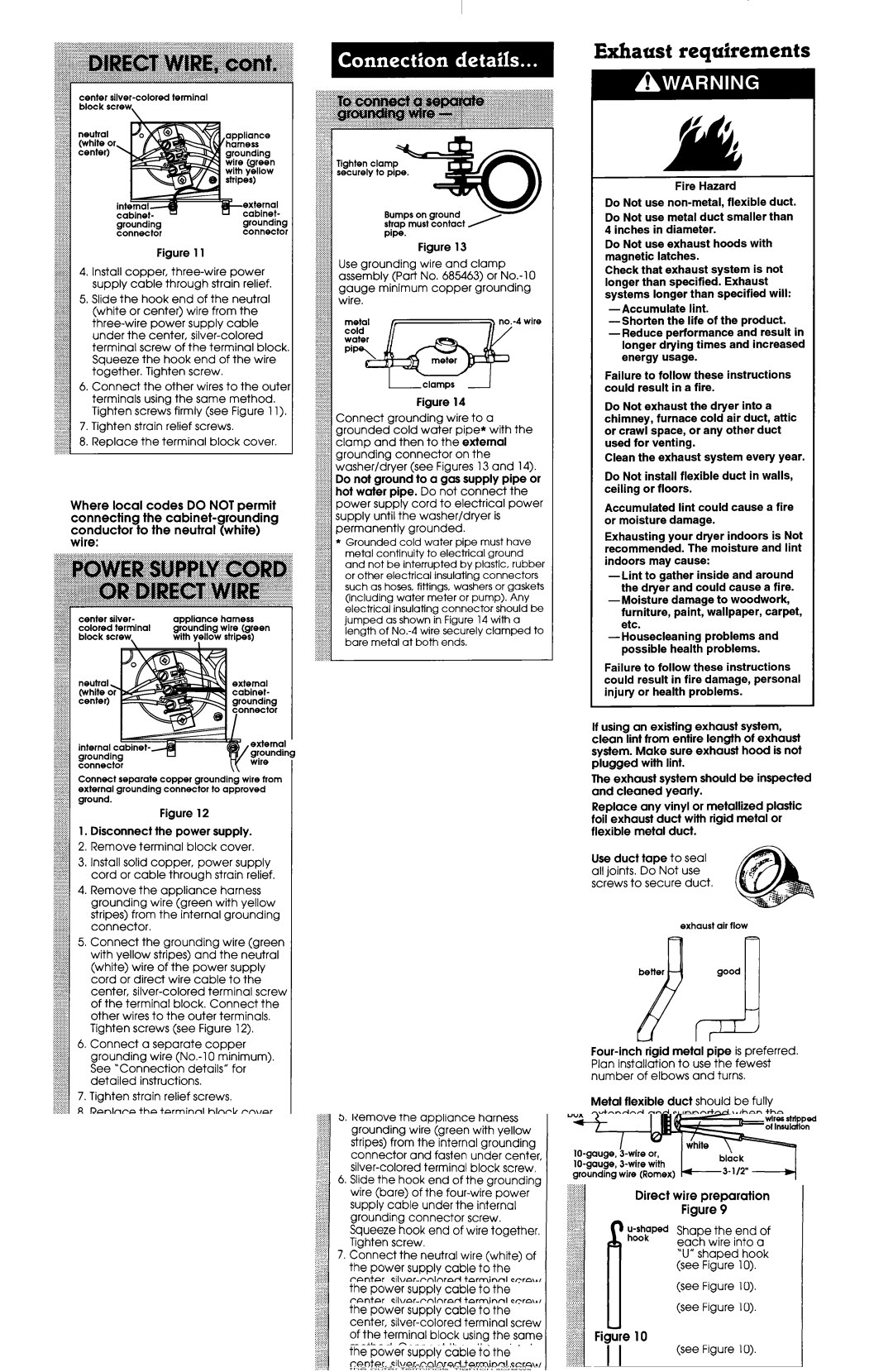
center silver-colored terminal
block | screw | \ |
| |
neutral | 01 | Efl,appliance |
(white | harness |
center) | | grounding |
| | 3Y/ e] St@+) |
external
cabinet---...--.ncabinet-
groundinggrounding
connectorconnector
Figure 11
4.Install copper, three-wire power supply cable through strain relief.
5.Slide the hook end of the neutral (white or center) wire from the three-wire power supply cable under the center, silver-colored terminal screw of the terminal block. Squeeze the hook end of the wire together. Tighten screw.
6.Connect the other wires to the outer terminals using the same method. Tighten screws firmly (see Figure 11).
7.Tighten strain relief screws.
8.Replace the terminal block cover.
Where local codes DO NOT permit connecting the cabinet-grounding conductor to the neutral (white) wire:
center | silver- | appliance | harness |
colored | terminal | grounding | wire (green |
block screw, | with y?llow | stripes) |
Connect separate copper grounding wire from external grounding connector to approved ground.
Figure 12
1.Disconnect fhe power supply.
2.Remove terminal block cover.
3.Install solid copper, power supply cord or cable through strain relief.
4.Remove the appliance harness grounding wire (green with yellow stripes) from the internal grounding connector.
5.Connect the grounding wire (green with yellow stripes) and the neutral (white) wire of the power supply cord or direct wire cable to the center, silver-colored terminal screw of the terminal block. Connect the other wires to the outer terminals. Tighten screws (see Figure 12).
6.Connect a separate copper grounding wire (No.-1 0 minimum). See “Connection details” for detailed instructions.
7.Tighten strain relief screws.
8.Replace the terminal block cover.
Tighten | clamp | r |
securely | to pipe. | I |
Bumps on ground strap must contact
Pipe.
Figure 13
Use grounding wire and clamp assembly (Part No. 685463) or No.-10 gauge minimum copper grounding wire.
coldmetal
I-I-clamps ‘-I
Figure 14
Connect grounding wire to a grounded cold water pipe* with the clamp and then to the external grounding connector on the washer/dryer (see Figures 13 and 14). Do not ground to a gas supply pipe or hot water pipe. Do not connect the power supply cord to electrical power supply until the washer/dryer is permanently grounded.
*Grounded cold water pipe must have metal continuity to electrical ground and not be interrupted by plastic, rubber or other electrical insulating connectors such as hoses, fittings, washers or gaskets (including water meter or pump). Any electrical insulating connector should be jumped as shown in Figure 14 with a length of No.-4 wire securely clamped to bare metal at both ends.
Exhaust requirements
f’ fI AL
Fire Hazard
Do Not use non-metal, flexible duct.
Do Not use metal duct smaller than 4 inches in diameter.
Do Not use exhaust hoods with magnetic latches.
Check that exhaust system is not longer than specified. Exhaust systems longer than specified will:
-Accumulate lint.
-Shorten the life of the product.
-Reduce performance and result in longer drying times and increased energy usage.
Failure to follow these instructions could result in a fire.
Do Not exhaust the dryer into a chimney, furnace cold air duct, attic or crawl space, or any other duct used for venting.
Clean the exhaust system every year.
Do Not install flexible duct in walls, ceiling or floors.
Accumulated lint could cause a fire or moisture damage.
Exhausting your dryer indoors is Not recommended. The moisture and lint indoors may cause:
-Lint to gather inside and around the dryer and could cause a fire.
-Moisture damage to woodwork, furniture, paint, wallpaper, carpet, etc.
-Housecleaning problems and possible health problems.
Failure to follow these instructions could result in fire damage, personal injury or health problems.
If using an existing exhaust system, clean lint from entire length of exhaust system. Make sure exhaust hood is not plugged wifh lint.
The exhaust system should be inspected and cleaned yearly.
Replace any vinyl or metallized plastic foil exhaust duct with rigid metal or flexible metal duct.
Use duct tape to seal all joints. Do Not use screws to secure duct.
exhaust air flow
better
d
Four-inch rigid metal pipe is preferred. Plan installation to use the fewest number of elbows and turns.
Metal flexible duct should be fully extended and supported when the dryer is in its final position. DO NOT KINK OR CRUSHTHEDUCT. The metal flexible duct must be fully extended to allow adequate exhaust air to flow.
Allow as much room as possible when using elbows or making turns. Bend duct gradually to avoid kinking. Remove excess flexible duct to avoid sagging and kinking that may result in reduced air flow.