anti-tip bracket
range foot
anti-tip bracket
range foot
2-3/8"
2-3/8"

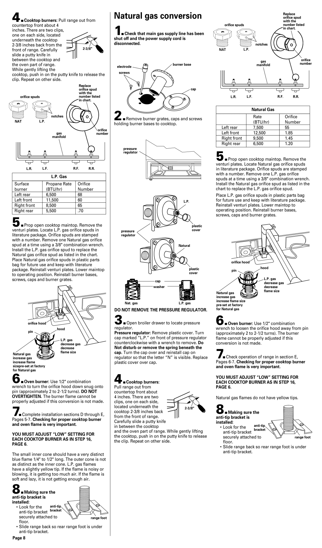
4.Cooktop burners: Pull range out from countertop front about 4

inches. There are two clips, one on each side, located underneath the cooktop

2-3/8 inches back from the front of range. Carefully slide a putty knife in

Natural gas conversion

1.Check that main gas supply line has been shut off and the power supply cord is disconnected.

Replace orifice spud with the

orifice spudsnumber listed in chart.


notches

NAT

L.P.

between the cooktop and the oven part of range. While gently lifting the

cooktop, push in on the putty knife to release the clip. Repeat on other side.


Replace


orifice spud


with the

orifice spuds

number listed


in chart.

electrode

screws

burner base

cap

gas

orifice

number

manifold


L.R.

L.F.

R.F.

R.R.


Natural Gas


notches


NAT

L.P.


gas

orifice


number


manifold


L.R.

L.F.

R.F.

R.R.


L.P. Gas


Surface

Propane Rate


Orifice

burner

(BTU/hr)


Number

Left rear

6,500


68


Left front

11,500


60


Right front

8,500


65


Right rear

5,500


.70


5.Prop open cooktop maintop. Remove the venturi plates. Locate L.P. gas orifice spuds in literature package. Orifice spuds are stamped with a number. Remove one Natural gas orifice spud at a time using a 3/8" combination wrench. Install the L.P. gas orifice spud to replace the Natural gas orifice spud as listed in the chart. Place Natural gas orifice spuds in plastic parts bag for future use and keep with literature package. Reinstall venturi plates. Lower maintop to operating position. Reinstall burner bases, screws, caps and burner grates.

orifice hood

pin

hood


L.P. gas


decrease gas


decrease

Natural gas

flame size


increase gas


increase flame


sizepre-set at factory


for Natural gas


6.Oven burner: Use 1/2" combination wrench to turn the orifice hood down snug onto pin (approximately 2 to 2-1/2 turns). DO NOT OVERTIGHTEN. The burner flame cannot be properly adjusted if this conversion is not made.

7.Complete installation sections D through E, Pages 5-7. Checking for proper cooktop burner and oven flame is very important.

YOU MUST ADJUST “LOW” SETTING FOR EACH COOKTOP BURNER AS IN STEP 16, PAGE 6.

The small inner cone should have a very distinct blue flame 1/4" to 1/2" long. The outer cone is not as distinct as the inner cone. L.P. gas flames have a slightly yellow tip. If the flame is noisy or blowing, it is getting too much air. If the flame is soft and lazy, it is not getting enough air.

8.Making sure the anti-tip bracket is installed:

• Look for the anti-tip bracket securely attached to floor.

Slide range back so rear range foot is under anti-tip bracket.

Page 8

2.Remove burner grates, caps and screws holding burner bases to cooktop.

pressure regulator

L.P.


plastic

pressure

cover


regulator


Natural

plastic cover

cap

washer

Nat. gas

L.P. gas

DO NOT REMOVE THE PRESSURE REGULATOR.

3.Open broiler drawer to locate pressure regulator.

Pressure regulator: Remove plastic cover. Turn cap marked “L.P.” on front of pressure regulator counterclockwise with a wrench to remove. Do

Not disturb or remove the spring beneath the cap. Turn the cap over and reinstall cap on regulator so that the letter “N” is visible. Replace plastic cover over cap.

4.Cooktop burners: Pull range out from countertop front about

4 inches. There are two clips, one on each side, located underneath the

cooktop 2-3/8 inches back from the front of range.

Carefully slide a putty knife in between the cooktop

and the oven part of range. While gently lifting the cooktop, push in on the putty knife to release the clip. Repeat on other side.


Rate

Orifice


(BTU/hr)

Number

Left rear

7,500

55

Left front

12,500

1.85

Right front

9,500

1.45

Right rear

6,500

1.20


5.Prop open cooktop maintop. Remove the venturi plates. Locate Natural gas orifice spuds in literature package. Orifice spuds are stamped with a number. Remove one L.P. gas orifice spuds at a time using a 3/8" combination wrench. Install the Natural gas orifice spud as listed in the chart to replace the L.P. gas orifice spud.

Place L.P. gas orifice spuds in plastic parts bag for future use and keep with literature package. Reinstall venturi plates. Lower maintop to operating position. Reinstall burner bases, screws, caps and burner grates.

orifice hood

pin

hood


L.P. gas


decrease gas


decrease

Natural gas

flame size


increase gas


increase flame size


pre-set at factory


for Natural gas


6.Oven burner: Use 1/2" combination wrench to loosen the orifice hood away from pin (approximately 2 to 2-1/2 turns). The burner flame cannot be properly adjusted if this conversion is not made.

7.Check operation of range in section E,

Pages 6-7.Checking for proper cooktop burner and oven flame is very important.

YOU MUST ADJUST “LOW” SETTING FOR EACH COOKTOP BURNER AS IN STEP 16, PAGE 6.

Natural gas flames do not have yellow tips.

8.Making sure the anti-tip bracket is installed:

• Look for the anti-tip bracket securely attached to floor.

Slide range back so rear range foot is under anti-tip bracket.

Page 8
Image 8
Whirlpool 8053365 Natural gas conversion, Cooktop burners Pull range out from countertop front about, Natural Gas

8053365 specifications

The Whirlpool 8053365 is a high-quality refrigerator water filter that has become increasingly popular among homeowners aiming to enhance their drinking water quality. Known for its efficient design and reliable performance, this water filter is engineered to reduce various impurities, ensuring that the water you consume is both safe and tasty.

One of the main features of the Whirlpool 8053365 is its ability to eliminate common contaminants found in tap water. This includes chlorine, sediment, and other impurities that might affect the taste and odor of your drinking water. By using advanced filtration technology, this water filter can remove up to 99% of various harmful substances, making it an excellent choice for health-conscious consumers.

The filter is easy to install, requiring no specialized tools or professional assistance. It connects seamlessly with compatible Whirlpool refrigerators, allowing homeowners to enjoy clean water and ice effortlessly. The quick connect design allows for hassle-free replacement, ensuring that users maintain fresh filtration without complicating their routine.

In terms of longevity, the Whirlpool 8053365 boasts an impressive lifespan, typically lasting up to six months or 200 gallons of water. This durability makes it an economical option for families and individuals who rely on consistent access to purified water. Regular replacement of the filter is essential to ensure optimal performance and to maintain water quality over time.

Another important characteristic of the Whirlpool 8053365 is its certification. This filter meets rigorous standards set forth by the NSF International, an independent organization that certifies water filtration products. This certification gives consumers peace of mind, knowing their filter has been tested for effectiveness and safety.

Overall, the Whirlpool 8053365 is a well-designed water filter that combines efficiency, durability, and ease of use. With its ability to improve water quality and compatibility with various Whirlpool refrigerator models, it remains a go-to choice for homeowners looking for a dependable water filtration solution. Whether for drinking water or ice production, this filter stands out as a practical investment in better health and quality of life.