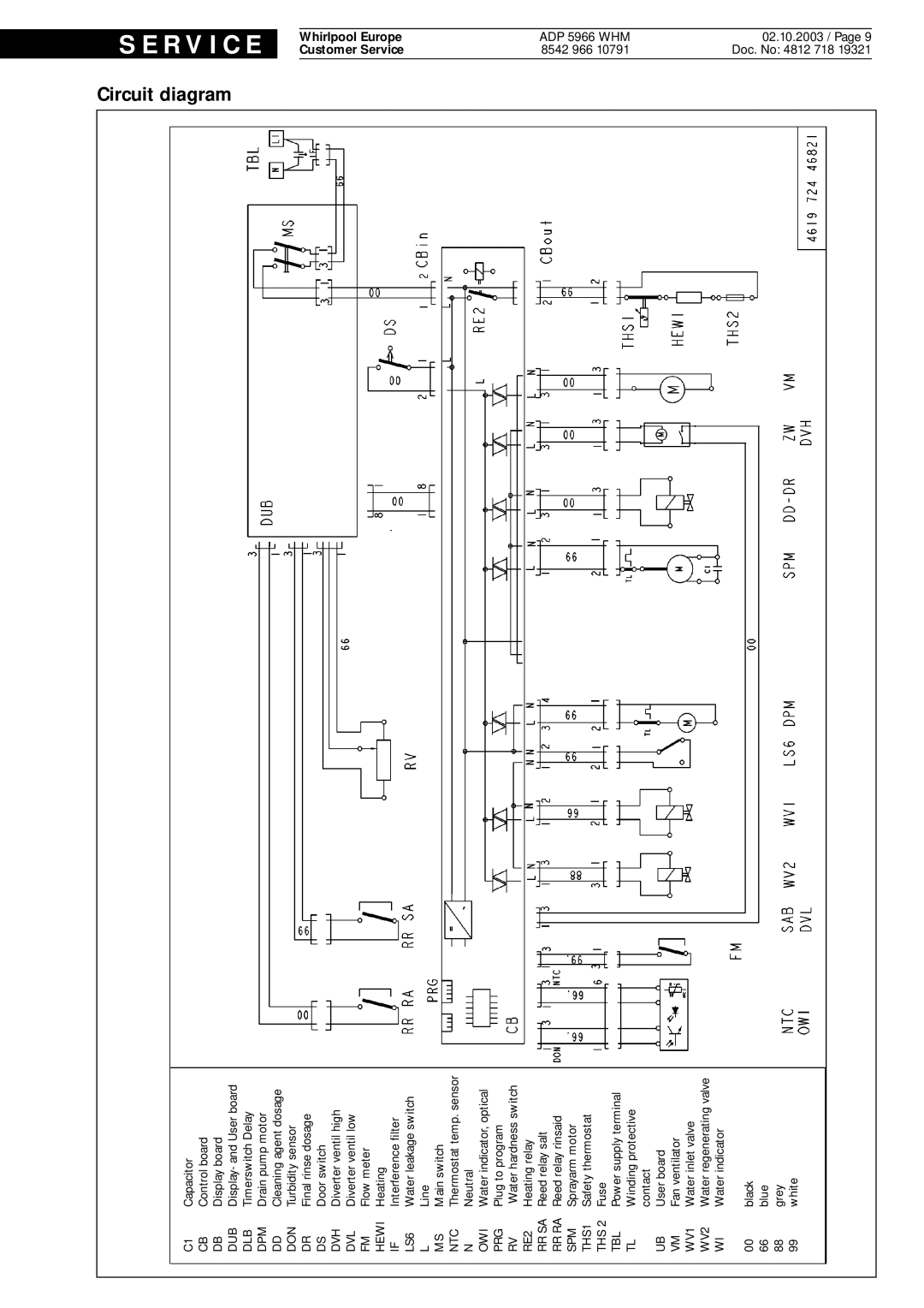
C1 | Capacitor |
CB | Control board |
DB | Display board |
DUB | Display- and User board |
DLB | Timerswitch Delay |
DPM | Drain pump motor |
DD | Cleaning agent dosage |
DON | Turbidity sensor |
DR | Final rinse dosage |
DS | Door switch |
DVH | Diverter ventil high |
DVL | Diverter ventil low |
FM | Flow meter |
HEWI | Heating |
IF | Interference filter |
LS6 | Water leakage switch |
L | Line |
MS | Main switch |
NTC | Thermostat temp. sensor |
N | Neutral |
OWI | Water indicator, optical |
PRG | Plug to program |
RV | Water hardness switch |
RE2 | Heating relay |
RR SA | Reed relay salt |
RR RA | Reed relay rinsaid |
SPM | Sprayarm motor |
THS1 | Safety thermostat |
THS 2 | Fuse |
TBL | Power supply terminal |
TL | Winding protective |
| contact |
UB | User board |
VM | Fan ventilator |
WV1 | Water inlet valve |
WV2 | Water regenerating valve |
WI | Water indicator |
00 | black |
66 | blue |
88grey
99white
Circuit | S E |
diagram | R V I C |
| E |
|
|
| Whirlpool Europe Customer Service |
8542 966 | ADP 5966 |
10791 | WHM |
02.10.2003 / Page 9 Doc. No: 4812 718 19321
