!CAUTION
To prevent electrical shock and/or equipment damage, disconnect electrical power to system, at main fuse or circuit breaker, until installation is complete.
!FAN CAUTION
To prevent personal injury and/or equipment dam- age, check equipment manufacturer’s wiring of fan relay circuit when in EMER HEAT. When the thermostat system switch is in the EMER HEAT position, the thermostat DOES NOT energize the fan relay when the fan switch is in the AUTO position.
NOTE
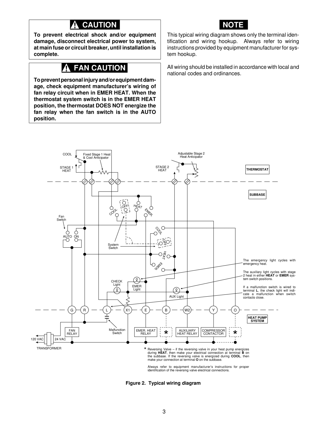
This typical wiring diagram shows only the terminal iden- tification and wiring hookup. Always refer to wiring instructions provided by equipment manufacturer for sys- tem hookup.
All wiring should be installed in accordance with local and national codes and ordinances.
COOL |
| Fixed Stage 1 Heat |
|
|
| Adjustable Stage 2 | ||||
|
| & Cool Anticipator |
|
|
|
| Heat Anticipator | |||
STAGE 1 |
|
|
| STAGE 2 |
|
|
|
|
| |
|
|
|
|
|
|
|
| |||
HEAT |
|
|
| HEAT |
|
|
|
|
| |
|
|
|
|
|
|
|
|
|
|
|
|
|
|
|
|
|
|
|
|
|
|
THERMOSTAT
SUBBASE
Fan
Switch
OFF | HEAT |
COOL | EMER |
. |
AUTO ON
System
Switch
CHECK
Light EMER
Light
COOL
OFF
HEAT
.EMER
The emergency light cycles with emergency heat.
The auxiliary light cycles with stage 2 heat in either HEAT or EMER sys- tem switch positions.
If a malfunction switch is wired to terminal L, the check light will indi- cate a malfunction when switch
AUX Light
contacts close.
120 VAC
G | R | L | X1 |
FAN |
|
| Malfunction |
RELAY |
|
| Switch |
24 VAC
E | B | W2 | Y | O |
|
|
|
| HEAT PUMP |
|
|
|
| SYSTEM |
EMER. HEAT | * | AUXILIARY | COMPRESSOR | * |
RELAY | HEAT RELAY | CONTACTOR |
TRANSFORMER | * Reversing Valve – if the reversing valve in your heat pump energizes |
| |
| during HEAT, then make your electrical connection at terminal B on |
| the subbase. If the reversing valve is energized during COOL, then |
| make your connection at terminal O on the subbase. |
| Always refer to equipment manufacturer’s instructions for proper |
| identification of the reversing valve electrical connections. |
| Figure 2. Typical wiring diagram |
3