1F85-275 specifications
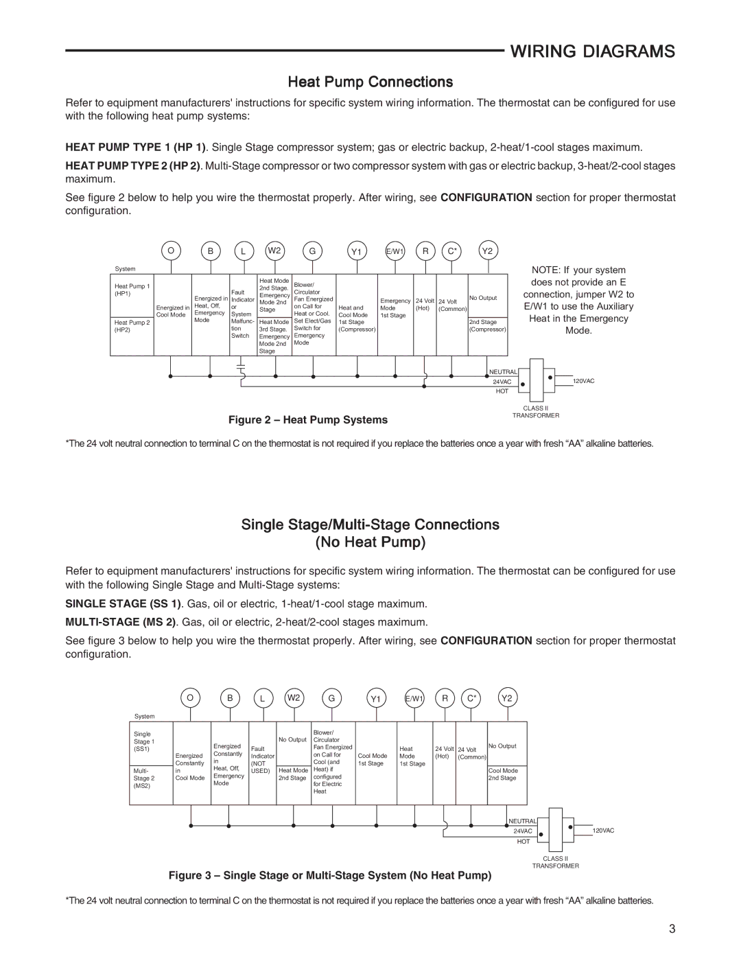
The White Rodgers 1F85-275 is a versatile and innovative thermostat designed to provide homeowners with precise control over their heating and cooling systems. Its user-friendly interface and advanced technologies make it a popular choice for those looking to optimize their indoor climate efficiently.One of the standout features of the 1F85-275 is its ability to control both heating and cooling systems, making it an all-in-one solution for year-round comfort. This thermostat is compatible with a wide range of HVAC systems, including gas, oil, electric, and heat pump systems. This compatibility ensures that homeowners can easily integrate the 1F85-275 into their existing setup without the need for extensive modifications.
A key characteristic of the 1F85-275 is its large, easy-to-read display. The digital interface allows users to view and adjust the temperature settings effortlessly. Additionally, the backlit display makes it convenient to read in low-light conditions, ensuring that adjustments can be made at any time of the day.
The 1F85-275 incorporates advanced scheduling capabilities, allowing homeowners to set specific temperature programs for different times of the day and days of the week. This feature promotes energy efficiency by enabling users to reduce heating or cooling when they are not at home or during sleeping hours. The intuitive programming options make it easy to customize settings according to individual preferences and lifestyles.
Another notable technology feature is the thermostat’s adaptive recovery capability. This technology automatically learns how long it takes for the home to reach the desired temperature, allowing it to start heating or cooling ahead of time. This ensures the home reaches the set temperature at the designated time, providing maximum comfort when needed most.
Moreover, the 1F85-275 includes a filter change indicator, reminding users when it’s time to replace or clean air filters. This not only enhances the efficiency of the HVAC system but also contributes to better indoor air quality.
The thermostat is also designed with energy-saving features in mind. Its precise temperature control and scheduling options can lead to significant savings on energy bills over time. With easy installation and clear instructions, users can have their 1F85-275 up and running in no time, making it an excellent choice for both tech-savvy users and those new to smart home technology.
In summary, the White Rodgers 1F85-275 combines user-friendly features, advanced technology, and energy-efficient operation, making it a compelling choice for homeowners seeking to enhance their indoor comfort while keeping energy costs in check.

