B O Y

NOTE

RED jumper wire (provided with thermostat) must be connected between thermo- stat'sRH and RC terminals for proper thermostat oper- ation with this system.

JUMPER

WIRE

G

W

RC

RH

THERMOSTAT

SYSTEM


Fan

Heating


Relay

System


Hot


24 VAC

120 VAC


Neutral


TRANSFORMER

THERMOSTAT

B O Y

G

W

RC RH

Cooling

Fan

Heating

System

Relay

System


SYSTEM


Hot


24 VAC


120 VAC


Neutral


HEATING TRANSFORMER

24 VAC


Hot


120 VAC


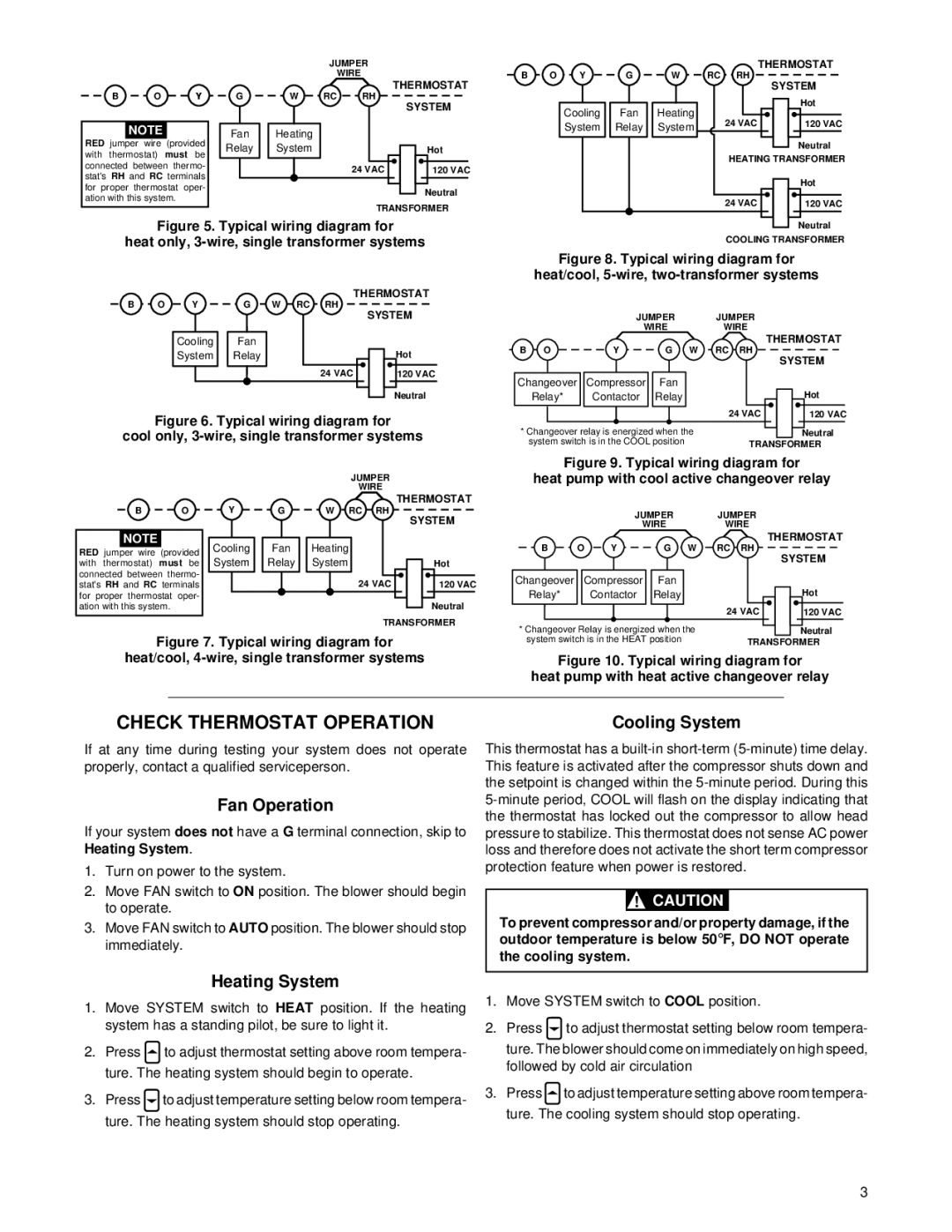
Figure 5. Typical wiring diagram for

heat only, 3-wire, single transformer systems

B

O

Y

G W RC RH

THERMOSTAT

SYSTEM


Cooling

Fan


System

Relay

Hot


24 VAC

120 VAC


Neutral

Figure 6. Typical wiring diagram for

cool only, 3-wire, single transformer systems


JUMPER


WIRE


Y


THERMOSTAT

B

O

G

W RC RH


SYSTEM


NOTE


Cooling


Fan


Heating


RED jumper wire

(provided


System


Relay


System


with thermostat)

must be


Hot

connected between thermo-


24 VAC


120 VAC

stat'sRH and RC terminals


for proper thermostat oper-


Neutral

ation with this system.


TRANSFORMER

Figure 7. Typical wiring diagram for

heat/cool, 4-wire, single transformer systems

Neutral

COOLING TRANSFORMER

Figure 8. Typical wiring diagram for

heat/cool, 5-wire, two-transformer systems


JUMPER


WIRE

B O

Y

G W

Changeover

Compressor

Fan

Relay*

Contactor

Relay

*Changeover relay is energized when the system switch is in the COOL position

JUMPER

WIRE

THERMOSTAT

RC RH

SYSTEM

Hot

24 VAC

120 VAC

Neutral

TRANSFORMER

Figure 9. Typical wiring diagram for

heat pump with cool active changeover relay


JUMPER


WIRE

B

O

Y

G W

Changeover

Compressor

Fan

Relay*


Contactor

Relay

*Changeover Relay is energized when the system switch is in the HEAT position

JUMPER

WIRE

THERMOSTAT

RC RH

SYSTEM


Hot

24 VAC

120 VAC

Neutral

TRANSFORMER

Figure 10. Typical wiring diagram for

heat pump with heat active changeover relay

CHECK THERMOSTAT OPERATION

If at any time during testing your system does not operate properly, contact a qualified serviceperson.

Fan Operation

If your system does not have a G terminal connection, skip to Heating System.

1.Turn on power to the system.

2.Move FAN switch to ON position. The blower should begin to operate.

3.Move FAN switch to AUTO position. The blower should stop immediately.

Cooling System

This thermostat has a built-in short-term (5-minute) time delay. This feature is activated after the compressor shuts down and the setpoint is changed within the 5-minute period. During this 5-minute period, COOL will flash on the display indicating that the thermostat has locked out the compressor to allow head pressure to stabilize. This thermostat does not sense AC power loss and therefore does not activate the short term compressor protection feature when power is restored.

!CAUTION

To prevent compressor and/or property damage, if the outdoor temperature is below 50°F, DO NOT operate the cooling system.

Heating System

1.Move SYSTEM switch to HEAT position. If the heating system has a standing pilot, be sure to light it.

2.Press to adjust thermostat setting above room tempera- ture. The heating system should begin to operate.

3.Pressto adjust temperature setting below room tempera- ture. The heating system should stop operating.

1.Move SYSTEM switch to COOL position.

2.Press to adjust thermostat setting below room tempera- ture. The blower should come on immediately on high speed, followed by cold air circulation

3.Pressto adjust temperature setting above room tempera- ture. The cooling system should stop operating.

3

Page 3
Image 3
White Rodgers 1F86-444 specifications Check Thermostat Operation, Fan Operation, Cooling System, Heating System

1F86-444 specifications

The White Rodgers 1F86-444 is a sophisticated digital thermostat designed to enhance heating and cooling system efficiency in residential and light commercial applications. As part of the White Rodgers family, this model exhibits an array of advanced features that cater to the user’s comfort while promoting energy savings.

One of the standout characteristics of the 1F86-444 is its easy-to-read, backlit LCD display. This feature ensures that users can view and adjust settings effortlessly, even in low light environments. The display not only shows the current temperature but also allows for programming and setting adjustments with clear, intuitive icons and text.

This thermostat is equipped with a user-friendly programmable schedule, enabling homeowners to set specific times for heating and cooling. With up to four programmable periods per day and the ability to tailor different schedules for weekdays and weekends, users can optimize their energy consumption while maintaining a comfortable home atmosphere.

The 1F86-444 also incorporates advanced technologies such as Adaptive Intelligent Recovery. This feature learns the heating and cooling characteristics of the home, allowing the thermostat to adjust the system's operation proactively. The goal is to reach the desired temperature by the scheduled time without overusing energy, thus preventing unnecessary costs on utility bills.

Another significant attribute is its versatile compatibility. The thermostat is designed to work with a wide range of HVAC systems, including 24V gas, oil, or electric heating systems, as well as conventional or heat pump cooling systems. This makes it a convenient option for homeowners with varying system types.

Additionally, the thermostat offers precise temperature control with a 1-degree accuracy, ensuring that users can maintain their desired comfort levels consistently. With features like an easily accessible battery backup, the thermostat retains programmed settings in case of a power outage, ensuring peace of mind.

In terms of installation, the 1F86-444 is designed for straightforward mounting, with a robust design that enhances its durability. Users can easily install it without requiring extensive technical skills, making it a practical choice for the DIY homeowner.

In summary, the White Rodgers 1F86-444 combines user-friendly design, advanced programming capabilities, and compatibility with a range of HVAC systems, making it an ideal solution for those looking to enhance their home’s comfort and energy efficiency. Its intelligent features and precise control set it apart in the digital thermostat market.