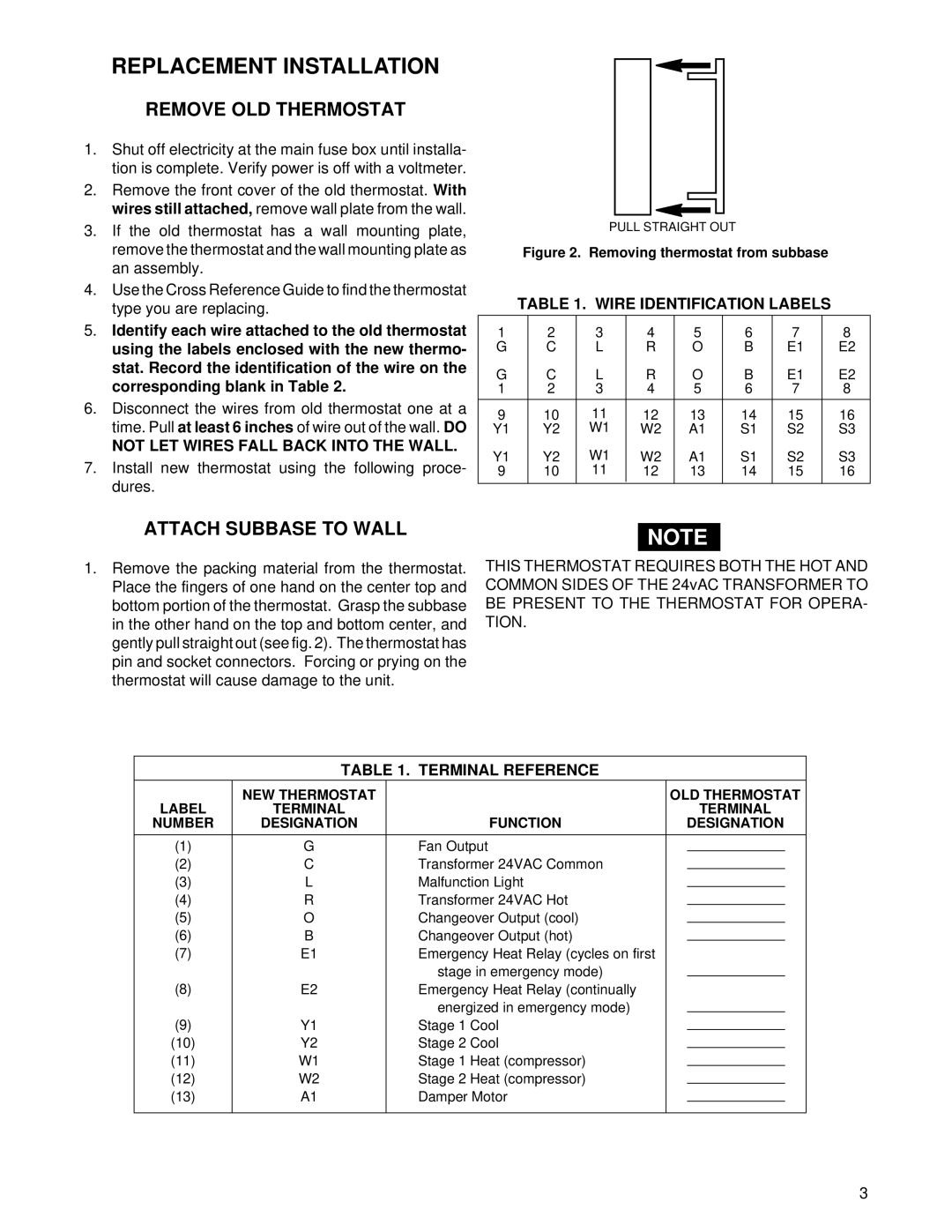
1F94-80 specifications
The White Rodgers 1F94-80 is an advanced thermostat designed to enhance home comfort and energy efficiency. This model stands out in the realm of smart thermostats due to its comprehensive features that cater to modern heating and cooling needs.One of the hallmark characteristics of the 1F94-80 is its user-friendly interface. The device is equipped with a large, backlit touchscreen display that enables easy navigation through various settings, even in low-light conditions. This intuitive design makes it accessible to users of all ages, allowing for straightforward temperature adjustments and programming.
A key feature is its five+two-day scheduling capability, allowing homeowners to set different heating and cooling programs for weekdays and weekends. This flexibility optimizes energy usage by aligning temperature changes with the household's daily routine, making it both cost-effective and environmentally friendly.
The White Rodgers 1F94-80 also incorporates advanced technology, such as Adaptive Intelligent Recovery, which learns how long it takes to heat or cool a space. This feature ensures that the desired temperature is reached by the scheduled time, preventing energy waste. Additionally, the thermostat uses Smart Diagnostic capabilities, providing troubleshooting information and alerts, thus making maintenance hassle-free.
For those keen on home automation, the 1F94-80 is compatible with various smart home systems. This allows users to integrate their thermostat with other smart devices, enabling remote control via mobile apps, voice commands, or automation setups. This level of connectivity enhances user convenience and control over their home environment.
Another noteworthy characteristic is its energy-saving modes. The thermostat offers a range of features aimed at reducing energy consumption, including a 'Hold' feature to temporarily adjust settings without resetting the entire schedule. This makes it easy for users to adapt to unexpected changes or special occasions without compromising their energy efficiency goals.
Safety and reliability are also key elements of the White Rodgers 1F94-80. The device is built with a robust design and includes features such as a filter change reminder, ensuring that heating and cooling systems operate at peak efficiency.
In summary, the White Rodgers 1F94-80 thermostat combines user-friendly technology, advanced scheduling, smart diagnostic features, and energy-saving modes. It represents a significant step in home climate control and efficiency, making it a strong choice for homeowners seeking reliability and comfort.

