NOTE

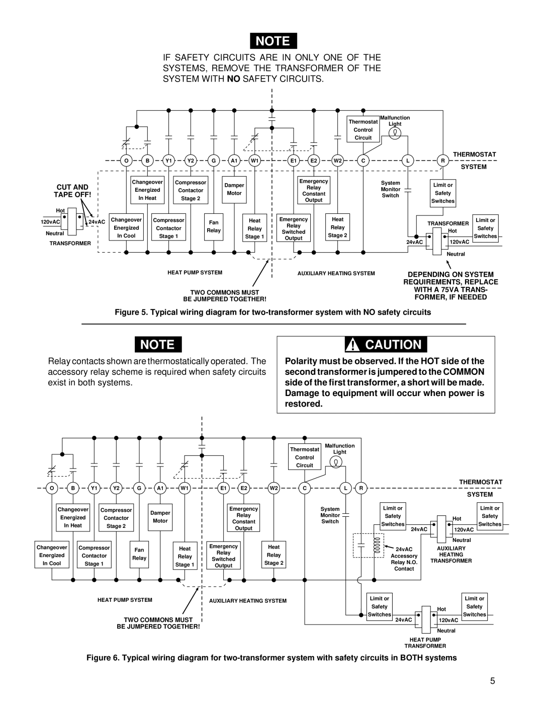
IF SAFETY CIRCUITS ARE IN ONLY ONE OF THE SYSTEMS, REMOVE THE TRANSFORMER OF THE SYSTEM WITH NO SAFETY CIRCUITS.

CUT AND

TAPE OFF!

Hot

120vAC

24vAC

Neutral

TRANSFORMER

O

B

Y1

Y2

G

A1

W1

Changeover

Compressor


Damper


Energized

Contactor


Motor


In Heat

Stage 2


Changeover


Compressor

Fan


Heat

Energized


Contactor


Relay


Relay


In Cool


Stage 1


Stage 1


HEAT PUMP SYSTEM

TWO COMMONS MUST

BE JUMPERED TOGETHER!

Thermostat

Control

Circuit

E1

E2

W2

C

Emergency

Relay

Constant

Output


Emergency


Heat

Relay


Relay

Switched


Stage 2

Output


AUXILIARY HEATING SYSTEM

Malfunction

Light

THERMOSTAT

L


R


System


SYSTEM


Limit or


Monitor


Safety


Switch


Switches


TRANSFORMER

Limit or


Safety


Hot


Switches


24vAC


120vAC


Neutral


DEPENDING ON SYSTEM REQUIREMENTS, REPLACE WITH A 75VA TRANS-

FORMER, IF NEEDED

Figure 5. Typical wiring diagram for two-transformer system with NO safety circuits

NOTE

Relay contacts shown are thermostatically operated. The accessory relay scheme is required when safety circuits exist in both systems.

!CAUTION

Polarity must be observed. If the HOT side of the second transformer is jumpered to the COMMON side of the first transformer, a short will be made. Damage to equipment will occur when power is restored.

Thermostat

Malfunction

Light

Control


Circuit


O

B

Y1


Y2


G

A1

W1


Changeover


Compressor


Damper


Energized


Contactor


Motor


In Heat


Stage 2


Changeover


Compressor


Fan


Heat

Energized


Contactor


Relay


Relay

In Cool


Stage 1


Stage 1


E1 E2

Emergency

Relay

Constant

Output

Emergency

Relay

Switched

Output

W2

C

L R

System

Monitor

Switch

Heat

Relay

Stage 2


THERMOSTAT


SYSTEM


Limit or


Limit or


Safety


Hot

Safety


Switches


Switches


24vAC


120vAC


Neutral


24vAC


AUXILIARY


Accessory


HEATING


Relay N.O.


TRANSFORMER


Contact


HEAT PUMP SYSTEM

AUXILIARY HEATING SYSTEM

TWO COMMONS MUST

BE JUMPERED TOGETHER!

Limit or

Safety

Switches


Limit or


Hot

Safety


Switches


24vAC


120vAC


Neutral

HEAT PUMP

TRANSFORMER

Figure 6. Typical wiring diagram for two-transformer system with safety circuits in BOTH systems

5

Page 5
Image 5
White Rodgers 1F94-80 installation instructions CUT Tape OFF

1F94-80 specifications

The White Rodgers 1F94-80 is an advanced thermostat designed to enhance home comfort and energy efficiency. This model stands out in the realm of smart thermostats due to its comprehensive features that cater to modern heating and cooling needs.

One of the hallmark characteristics of the 1F94-80 is its user-friendly interface. The device is equipped with a large, backlit touchscreen display that enables easy navigation through various settings, even in low-light conditions. This intuitive design makes it accessible to users of all ages, allowing for straightforward temperature adjustments and programming.

A key feature is its five+two-day scheduling capability, allowing homeowners to set different heating and cooling programs for weekdays and weekends. This flexibility optimizes energy usage by aligning temperature changes with the household's daily routine, making it both cost-effective and environmentally friendly.

The White Rodgers 1F94-80 also incorporates advanced technology, such as Adaptive Intelligent Recovery, which learns how long it takes to heat or cool a space. This feature ensures that the desired temperature is reached by the scheduled time, preventing energy waste. Additionally, the thermostat uses Smart Diagnostic capabilities, providing troubleshooting information and alerts, thus making maintenance hassle-free.

For those keen on home automation, the 1F94-80 is compatible with various smart home systems. This allows users to integrate their thermostat with other smart devices, enabling remote control via mobile apps, voice commands, or automation setups. This level of connectivity enhances user convenience and control over their home environment.

Another noteworthy characteristic is its energy-saving modes. The thermostat offers a range of features aimed at reducing energy consumption, including a 'Hold' feature to temporarily adjust settings without resetting the entire schedule. This makes it easy for users to adapt to unexpected changes or special occasions without compromising their energy efficiency goals.

Safety and reliability are also key elements of the White Rodgers 1F94-80. The device is built with a robust design and includes features such as a filter change reminder, ensuring that heating and cooling systems operate at peak efficiency.

In summary, the White Rodgers 1F94-80 thermostat combines user-friendly technology, advanced scheduling, smart diagnostic features, and energy-saving modes. It represents a significant step in home climate control and efficiency, making it a strong choice for homeowners seeking reliability and comfort.