INSTALLATION
!WARNING
Thermostat installation and all components of the control system shall conform to Class II circuits per the NEC code.
6.Push excess wire into wall and plug hole with a fire re- sistant material (such as fiberglass insulation) to prevent drafts from affecting thermostat operation.
7.Carefully line the thermostat up with the base and snap into place.
Battery Location
Remove Old Thermostat |
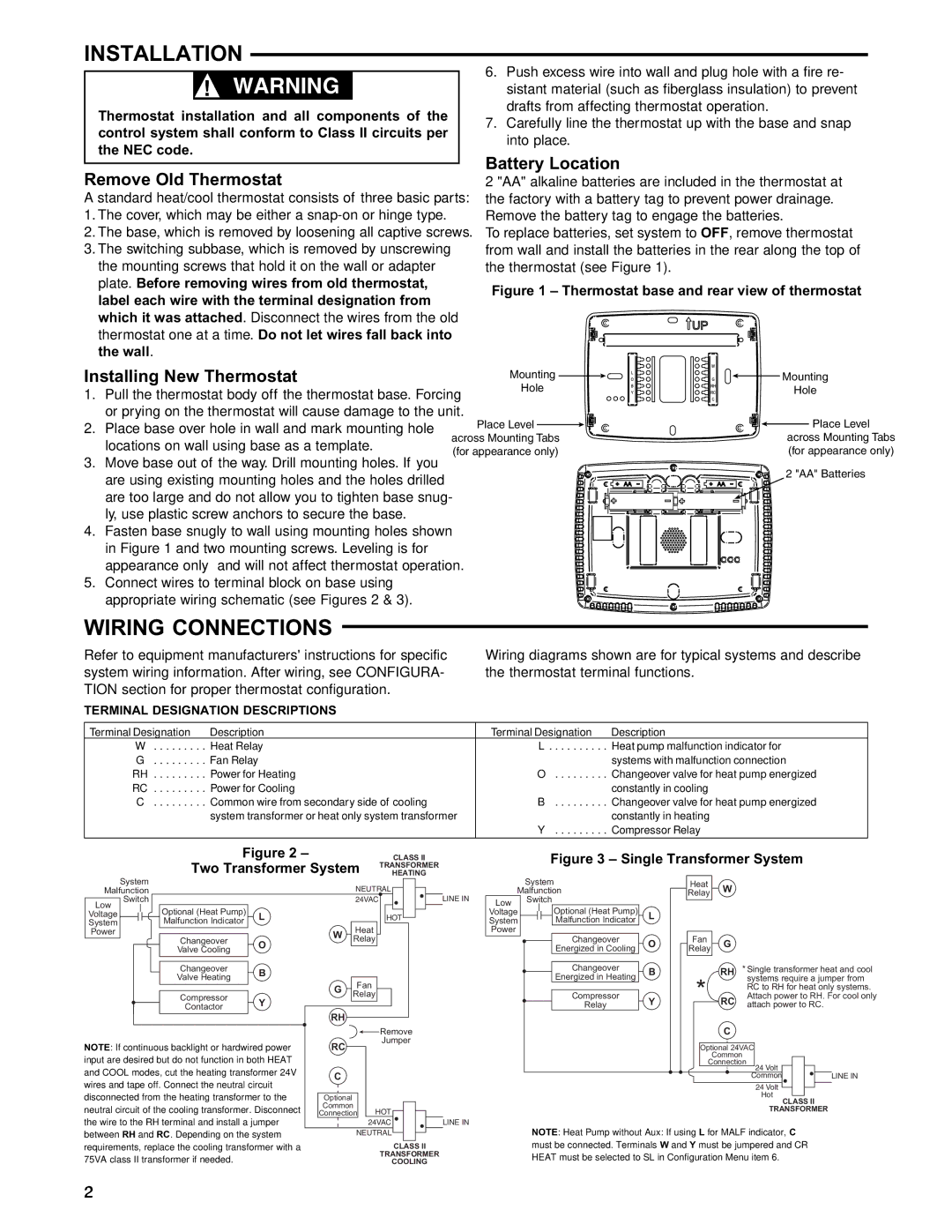
| 2 "AA" alkaline batteries are included in the thermostat at | |||||||||||||||
A standard heat/cool thermostat consists of three basic parts: | the factory with a battery tag to prevent power drainage. | ||||||||||||||||
1. The cover, which may be either a |
| Remove the battery tag to engage the batteries. | |||||||||||||||
2. The base, which is removed by loosening all captive screws. | To replace batteries, set system to OFF, remove thermostat | ||||||||||||||||
3. The switching subbase, which is removed by unscrewing |
| from wall and install the batteries in the rear along the top of | |||||||||||||||
the mounting screws that hold it on the wall or adapter |
| the thermostat (see Figure 1). |
|
|
|
|
| ||||||||||
plate. Before removing wires from old thermostat, |
| Figure 1 – Thermostat base and rear view of thermostat | |||||||||||||||
label each wire with the terminal designation from |
| ||||||||||||||||
|
|
|
|
|
|
|
|
|
|
|
|
|
|
|
|
| |
which it was attached. Disconnect the wires from the old |
|
|
|
|
|
|
|
|
|
|
|
|
|
|
|
| |
thermostat one at a time. Do not let wires fall back into |
|
|
|
|
|
|
|
|
|
|
|
|
|
|
|
| |
the wall. |
|
|
|
|
|
|
|
|
|
|
|
|
|
|
|
|
|
Installing New Thermostat |
| Mounting |
|
|
|
|
|
|
|
|
|
|
|
| Mounting | ||
|
|
|
|
|
|
| |||||||||||
1. Pull the thermostat body off the thermostat base. Forcing | Hole |
|
|
| Hole | ||||||||||||
|
|
|
|
|
|
|
|
|
|
|
|
|
| ||||
or prying on the thermostat will cause damage to the unit. | Place Level |
|
|
|
|
|
|
|
|
|
|
|
|
|
| Place Level | |
2. Place base over hole in wall and mark mounting hole |
|
|
|
|
|
|
|
|
|
|
|
|
| ||||
|
|
|
|
|
| ||||||||||||
locations on wall using base as a template. | across Mounting Tabs |
|
|
| across Mounting Tabs | ||||||||||||
(for appearance only) |
|
|
| (for appearance only) | |||||||||||||
3. Move base out of the way. Drill mounting holes. If you |
|
|
| ||||||||||||||
|
|
|
|
|
|
|
|
|
|
|
|
|
|
| 2 "AA" Batteries | ||
are using existing mounting holes and the holes drilled |
|
|
|
|
|
|
|
|
|
|
|
|
|
|
| ||
|
|
|
|
|
|
|
|
|
|
|
|
|
|
|
|
| |
are too large and do not allow you to tighten base snug- |
|
|
|
|
|
|
|
|
|
|
|
|
|
|
|
| |
|
|
|
|
|
|
|
|
|
|
|
|
|
|
|
| ||
ly, use plastic screw anchors to secure the base. |
|
|
|
|
|
|
|
|
|
|
|
|
|
|
|
|
|
|
|
|
|
|
|
|
|
|
|
|
|
|
|
|
|
| |
|
|
|
|
|
|
|
|
|
|
|
|
|
|
|
|
| |
4.Fasten base snugly to wall using mounting holes shown in Figure 1 and two mounting screws. Leveling is for appearance only and will not affect thermostat operation.
5.Connect wires to terminal block on base using appropriate wiring schematic (see Figures 2 & 3).
WIRING CONNECTIONS
Refer to equipment manufacturers' instructions for specific system wiring information. After wiring, see CONFIGURA- TION section for proper thermostat configuration.
TERMINAL DESIGNATION DESCRIPTIONS
Wiring diagrams shown are for typical systems and describe the thermostat terminal functions.
Terminal Designation | Description | Terminal Designation | Description |
W | Heat Relay | L | Heat pump malfunction indicator for |
G | Fan Relay |
| systems with malfunction connection |
RH | Power for Heating | O | Changeover valve for heat pump energized |
RC | Power for Cooling |
| constantly in cooling |
C | Common wire from secondary side of cooling | B | Changeover valve for heat pump energized |
| system transformer or heat only system transformer |
| constantly in heating |
|
| Y | Compressor Relay |
|
|
|
|
Figure 2 – | CLASS II |
Two Transformer System | TRANSFORMER |
HEATING |
Figure 3 – Single Transformer System
System |
|
|
Malfunction |
|
|
Switch |
|
|
Low | Optional (Heat Pump) |
|
Voltage | L | |
System | Malfunction Indicator |
|
Power | Changeover |
|
| O | |
| Valve Cooling | |
|
|
Changeover | B | |
Valve Heating | ||
| ||
Compressor | Y | |
Contactor | ||
|
NOTE: If continuous backlight or hardwired power input are desired but do not function in both HEAT and COOL modes, cut the heating transformer 24V wires and tape off. Connect the neutral circuit disconnected from the heating transformer to the neutral circuit of the cooling transformer. Disconnect the wire to the RH terminal and install a jumper between RH and RC. Depending on the system requirements, replace the cooling transformer with a 75VA class II transformer if needed.
| NEUTRAL |
| |
| 24VAC | LINE IN | |
|
| HOT |
|
W | Heat |
|
|
Relay |
| ||
G | Fan |
|
|
Relay |
|
| |
|
|
| |
RH |
|
|
|
|
| Remove |
|
RC |
| Jumper |
|
|
|
| |
C |
|
|
|
Optional |
|
|
|
Common | HOT |
| |
Connection | LINE IN | ||
| 24VAC | ||
| NEUTRAL |
| |
|
| CLASS II |
|
|
| TRANSFORMER |
|
|
| COOLING |
|
|
| System |
|
|
|
| Heat |
| W |
|
|
|
|
|
|
| |||||
| Malfunction |
|
|
|
| Relay |
|
|
|
|
|
|
|
| |||||||
Low |
| Switch |
|
|
|
|
|
|
|
|
|
|
|
|
|
|
|
| |||
|
|
|
|
|
|
|
|
|
|
|
|
|
|
|
| ||||||
Voltage |
|
|
|
|
| Optional (Heat Pump) |
| L |
|
|
|
|
|
|
|
|
|
|
|
|
|
System |
|
|
|
|
| Malfunction Indicator |
|
|
|
|
|
|
|
|
|
|
|
|
|
|
|
Power |
|
|
|
|
|
|
|
|
|
|
|
|
|
|
|
|
|
|
|
|
|
|
|
|
|
|
| Changeover |
| O |
|
| Fan |
| G |
|
|
|
|
|
|
| |
|
|
|
|
|
| Energized in Cooling |
|
|
|
| Relay |
|
|
|
|
|
|
|
|
| |
|
|
|
|
|
|
|
|
|
|
|
|
|
|
|
|
|
|
|
|
|
|
|
|
|
|
|
|
|
|
|
|
|
|
|
|
|
| ||||||
|
|
|
|
|
| Changeover |
| B |
|
|
|
|
| RH | * Single transformer heat and cool | ||||||
|
|
|
|
|
| Energized in Heating |
|
|
| * |
|
| systems require a jumper from | ||||||||
|
|
|
|
|
|
|
|
|
|
|
| RC to RH for heat only systems. | |||||||||
|
|
|
|
|
| Compressor |
| Y |
|
| RC | Attach power to RH. For cool only | |||||||||
|
|
|
|
|
| Relay |
|
|
|
|
|
|
| C | attach power to RC. |
| |||||
|
|
|
|
|
|
|
|
|
|
|
|
|
|
|
|
|
|
|
|
| |
|
|
|
|
|
|
|
|
|
|
|
|
|
|
|
|
|
|
|
|
| |
|
|
|
|
|
|
|
|
|
|
|
| Optional 24VAC |
|
|
|
|
|
| |||
|
|
|
|
|
|
|
|
|
|
|
|
| Common |
|
|
|
|
|
| ||
|
|
|
|
|
|
|
|
|
|
|
| Connection | 24 Volt |
|
|
|
|
| |||
|
|
|
|
|
|
|
|
|
|
|
|
|
|
| Common |
|
|
|
| LINE IN | |
|
|
|
|
|
|
|
|
|
|
|
|
|
|
|
| 24 Volt |
|
|
|
|
|
|
|
|
|
|
|
|
|
|
|
|
|
|
|
|
| Hot |
|
|
| ||
|
|
|
|
|
|
|
|
|
|
|
|
|
|
|
|
| CLASS II |
| |||
|
|
|
|
|
|
|
|
|
|
|
|
|
|
|
| TRANSFORMER |
| ||||
NOTE: Heat Pump without Aux: If using L for MALF indicator, C must be connected. Terminals W and Y must be jumpered and CR HEAT must be selected to SL in Configuration Menu item 6.
2