INSTALLATION (CONT.)
In this regard, do not locate the bulb too close to the heating element.
2.Care should be taken not to damage the capillary tubing between the switch and bulb of the control. Do not kink the capillary.
3.Do not dent or bend the control bulb as this will change the
control calibration and cause the control to cycle at a tem- perature lower than the dial setting.
4.The switch of the control may be mounted in any convenient
location provided that the ambient temperature surrounding the switch does not exceed 150°F (66°C).
SETTING
In most cases the equipment manufacturer has provided a dial to indicate the setting of the control. For a warmer setting, turn
knob or shaft clockwise. For a cooler setting, turn knob or shaft counterclockwise.
WIRING
All wiring should be done in accordance with local and national electrical codes and ordinances.
Follow any instructions provided by the equipment manufac- turer.
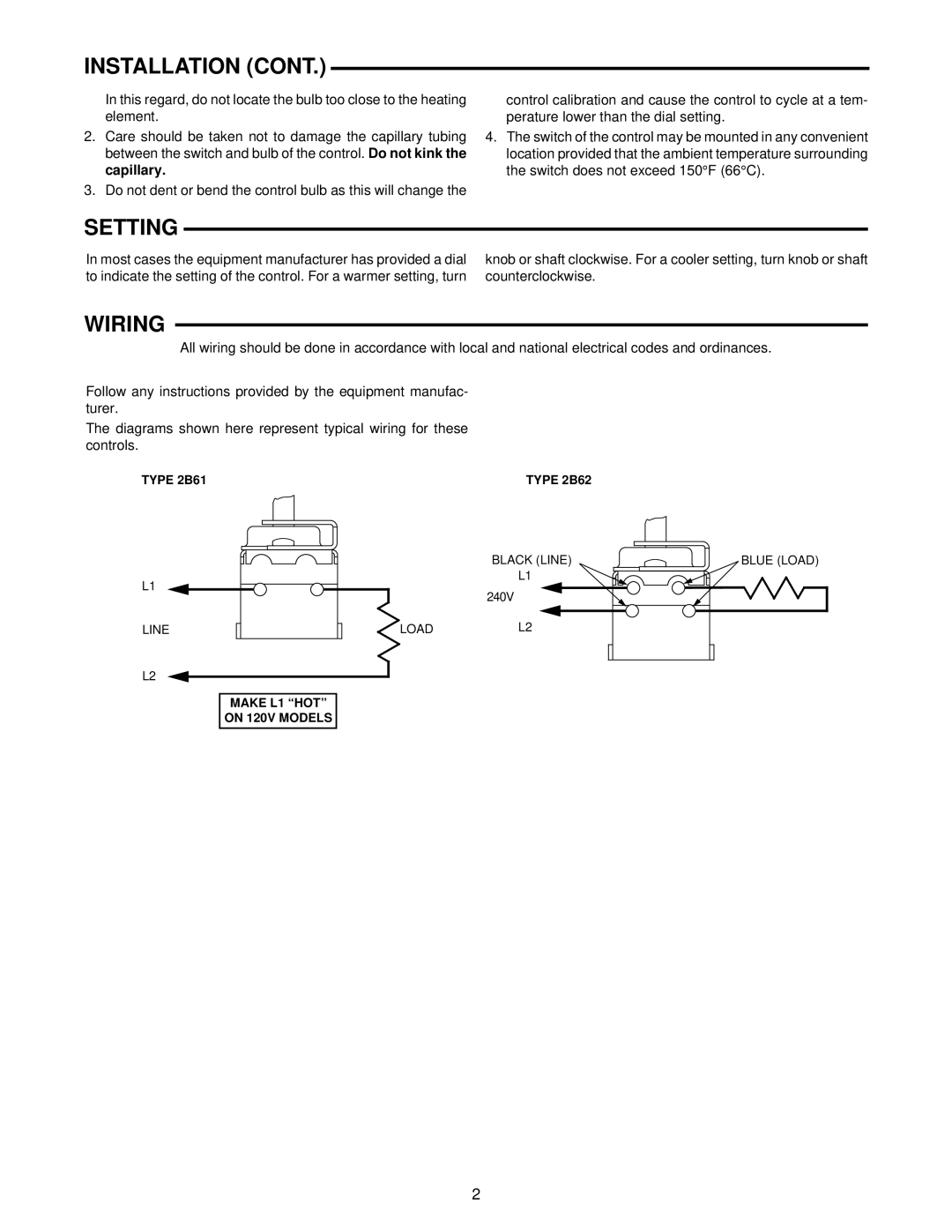
The diagrams shown here represent typical wiring for these controls.
TYPE 2B61
L1
LINE | LOAD |
L2
MAKE L1 “HOT”
ON 120V MODELS
TYPE 2B62
BLACK (LINE)
L1
240V
L2
BLUE (LOAD)
2