!CAUTION
To prevent electrical shock and/or equipment damage, disconnect electrical power to the sys- tem at the main fuse or circuit breaker box, until installation is complete.
NOTE
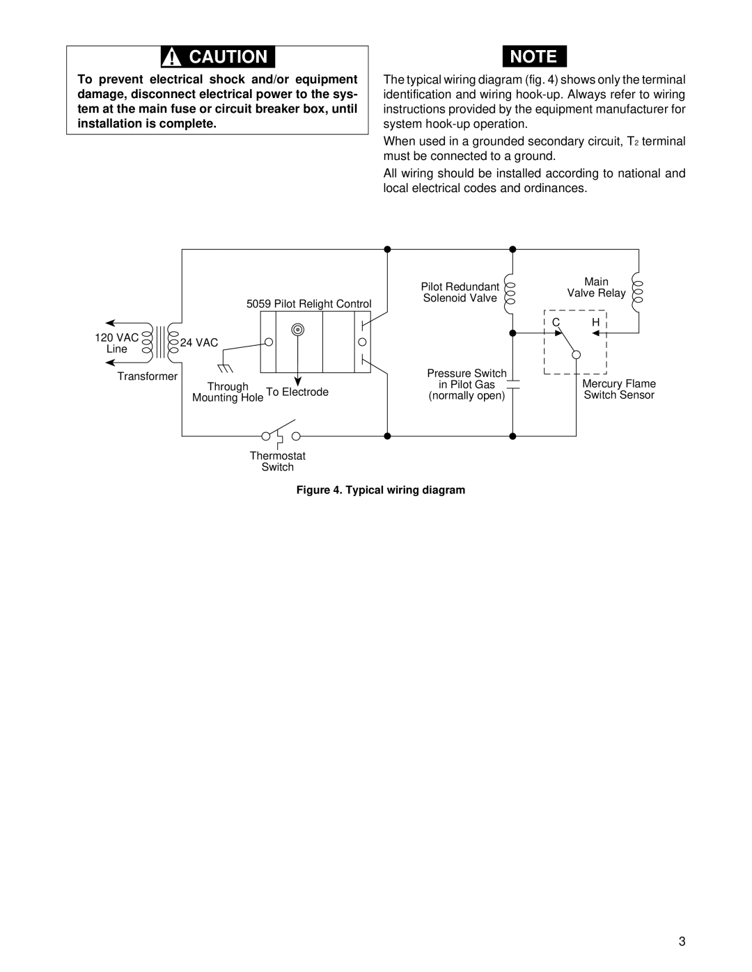
The typical wiring diagram (fig. 4) shows only the terminal identification and wiring
When used in a grounded secondary circuit, T2 terminal must be connected to a ground.
All wiring should be installed according to national and local electrical codes and ordinances.
|
| Pilot Redundant |
| 5059 Pilot Relight Control | Solenoid Valve |
|
| |
120 VAC | 24 VAC |
|
Line |
| |
|
| |
Transformer | Through | Pressure Switch |
| in Pilot Gas | |
| Mounting Hole To Electrode | (normally open) |
Thermostat
Switch
Figure 4. Typical wiring diagram
Main
Valve Relay
C H
Mercury Flame
Switch Sensor
3