OPERATION
OPTION SWITCHES
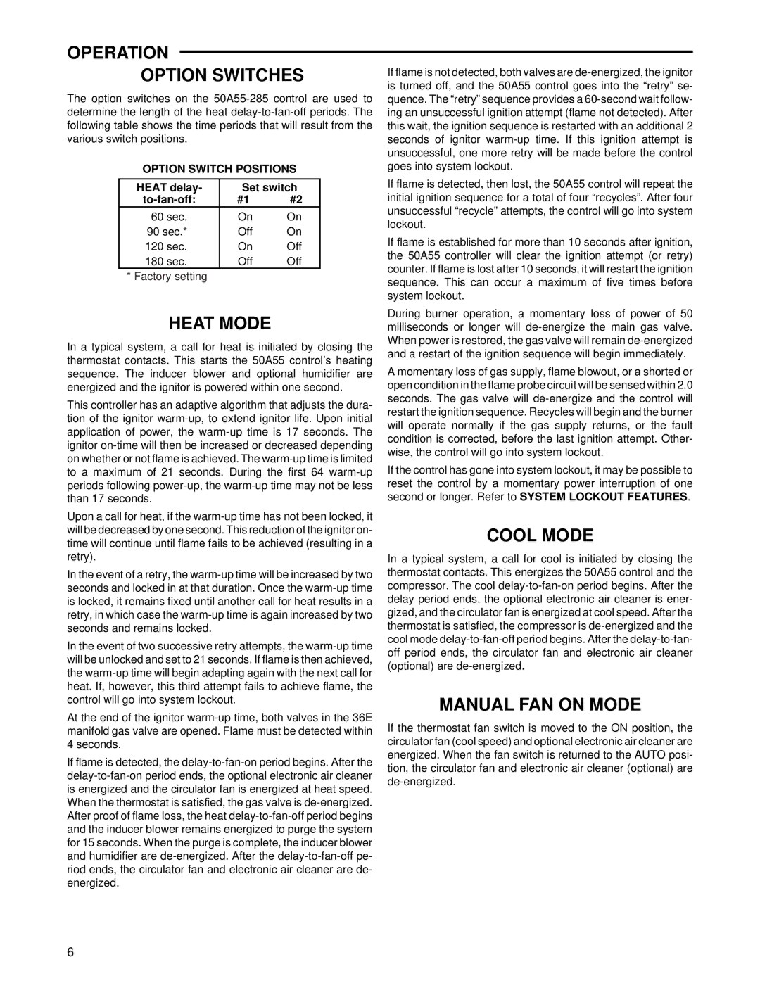
The option switches on the 50A55-285 control are used to determine the length of the heat delay-to-fan-off periods. The following table shows the time periods that will result from the various switch positions.
OPTION SWITCH POSITIONS
HEAT delay- | Set switch |
to-fan-off: | #1 | #2 |
60 sec. | On | On |
90 sec.* | Off | On |
120 sec. | On | Off |
180 sec. | Off | Off |
* Factory setting
HEAT MODE
In a typical system, a call for heat is initiated by closing the thermostat contacts. This starts the 50A55 control’s heating sequence. The inducer blower and optional humidifier are energized and the ignitor is powered within one second.
This controller has an adaptive algorithm that adjusts the dura- tion of the ignitor warm-up, to extend ignitor life. Upon initial application of power, the warm-up time is 17 seconds. The ignitor on-time will then be increased or decreased depending on whether or not flame is achieved. The warm-up time is limited to a maximum of 21 seconds. During the first 64 warm-up periods following power-up, the warm-up time may not be less than 17 seconds.
Upon a call for heat, if the warm-up time has not been locked, it will be decreased by one second. This reduction of the ignitor on- time will continue until flame fails to be achieved (resulting in a retry).
In the event of a retry, the warm-up time will be increased by two seconds and locked in at that duration. Once the warm-up time is locked, it remains fixed until another call for heat results in a retry, in which case the warm-up time is again increased by two seconds and remains locked.
In the event of two successive retry attempts, the warm-up time will be unlocked and set to 21 seconds. If flame is then achieved, the warm-up time will begin adapting again with the next call for heat. If, however, this third attempt fails to achieve flame, the control will go into system lockout.
At the end of the ignitor warm-up time, both valves in the 36E manifold gas valve are opened. Flame must be detected within 4 seconds.
If flame is detected, the delay-to-fan-on period begins. After the delay-to-fan-on period ends, the optional electronic air cleaner is energized and the circulator fan is energized at heat speed. When the thermostat is satisfied, the gas valve is de-energized. After proof of flame loss, the heat delay-to-fan-off period begins and the inducer blower remains energized to purge the system for 15 seconds. When the purge is complete, the inducer blower and humidifier are de-energized. After the delay-to-fan-off pe- riod ends, the circulator fan and electronic air cleaner are de- energized.
If flame is not detected, both valves are de-energized, the ignitor is turned off, and the 50A55 control goes into the “retry” se- quence. The “retry” sequence provides a 60-second wait follow- ing an unsuccessful ignition attempt (flame not detected). After this wait, the ignition sequence is restarted with an additional 2 seconds of ignitor warm-up time. If this ignition attempt is unsuccessful, one more retry will be made before the control goes into system lockout.
If flame is detected, then lost, the 50A55 control will repeat the initial ignition sequence for a total of four “recycles”. After four unsuccessful “recycle” attempts, the control will go into system lockout.
If flame is established for more than 10 seconds after ignition, the 50A55 controller will clear the ignition attempt (or retry) counter. If flame is lost after 10 seconds, it will restart the ignition sequence. This can occur a maximum of five times before system lockout.
During burner operation, a momentary loss of power of 50 milliseconds or longer will de-energize the main gas valve. When power is restored, the gas valve will remain de-energized and a restart of the ignition sequence will begin immediately.
A momentary loss of gas supply, flame blowout, or a shorted or open condition in the flame probe circuit will be sensed within 2.0 seconds. The gas valve will de-energize and the control will restart the ignition sequence. Recycles will begin and the burner will operate normally if the gas supply returns, or the fault condition is corrected, before the last ignition attempt. Other- wise, the control will go into system lockout.
If the control has gone into system lockout, it may be possible to reset the control by a momentary power interruption of one second or longer. Refer to SYSTEM LOCKOUT FEATURES.
COOL MODE
In a typical system, a call for cool is initiated by closing the thermostat contacts. This energizes the 50A55 control and the compressor. The cool delay-to-fan-on period begins. After the delay period ends, the optional electronic air cleaner is ener- gized, and the circulator fan is energized at cool speed. After the thermostat is satisfied, the compressor is de-energized and the cool mode delay-to-fan-off period begins. After the delay-to-fan- off period ends, the circulator fan and electronic air cleaner (optional) are de-energized.
MANUAL FAN ON MODE
If the thermostat fan switch is moved to the ON position, the circulator fan (cool speed) and optional electronic air cleaner are energized. When the fan switch is returned to the AUTO posi- tion, the circulator fan and electronic air cleaner (optional) are de-energized.
