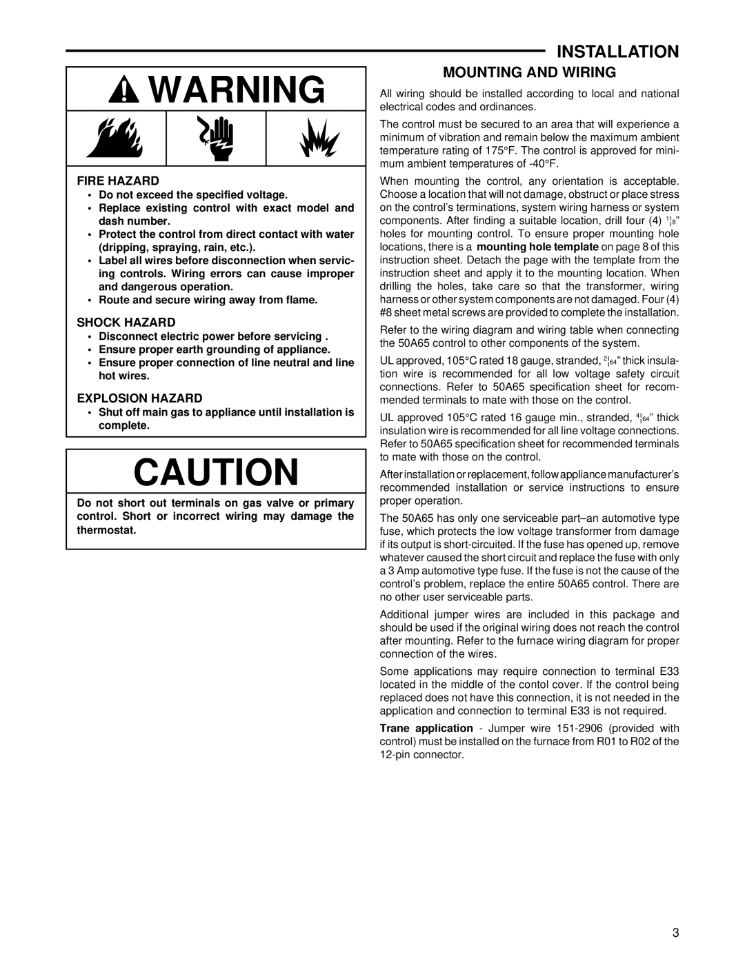
WARNING

FIRE HAZARD

Do not exceed the specified voltage.

Replace existing control with exact model and dash number.

Protect the control from direct contact with water (dripping, spraying, rain, etc.).

Label all wires before disconnection when servic- ing controls. Wiring errors can cause improper and dangerous operation.

Route and secure wiring away from flame.

SHOCK HAZARD

Disconnect electric power before servicing .

Ensure proper earth grounding of appliance.

Ensure proper connection of line neutral and line hot wires.

EXPLOSION HAZARD

Shut off main gas to appliance until installation is complete.

CAUTION

Do not short out terminals on gas valve or primary control. Short or incorrect wiring may damage the thermostat.

INSTALLATION

MOUNTING AND WIRING

All wiring should be installed according to local and national electrical codes and ordinances.

The control must be secured to an area that will experience a minimum of vibration and remain below the maximum ambient temperature rating of 175°F. The control is approved for mini- mum ambient temperatures of -40°F.

When mounting the control, any orientation is acceptable. Choose a location that will not damage, obstruct or place stress on the control’s terminations, system wiring harness or system components. After finding a suitable location, drill four (4) 1¦8” holes for mounting control. To ensure proper mounting hole locations, there is a mounting hole template on page 8 of this instruction sheet. Detach the page with the template from the instruction sheet and apply it to the mounting location. When drilling the holes, take care so that the transformer, wiring harness or other system components are not damaged. Four (4) #8 sheet metal screws are provided to complete the installation.

Refer to the wiring diagram and wiring table when connecting the 50A65 control to other components of the system.

UL approved, 105°C rated 18 gauge, stranded, 2¦64” thick insula- tion wire is recommended for all low voltage safety circuit connections. Refer to 50A65 specification sheet for recom- mended terminals to mate with those on the control.

UL approved 105°C rated 16 gauge min., stranded, 4¦64” thick insulation wire is recommended for all line voltage connections. Refer to 50A65 specification sheet for recommended terminals to mate with those on the control.

After installation or replacement, follow appliance manufacturer’s recommended installation or service instructions to ensure proper operation.

The 50A65 has only one serviceable part–an automotive type fuse, which protects the low voltage transformer from damage if its output is short-circuited. If the fuse has opened up, remove whatever caused the short circuit and replace the fuse with only a 3 Amp automotive type fuse. If the fuse is not the cause of the control’s problem, replace the entire 50A65 control. There are no other user serviceable parts.

Additional jumper wires are included in this package and should be used if the original wiring does not reach the control after mounting. Refer to the furnace wiring diagram for proper connection of the wires.

Some applications may require connection to terminal E33 located in the middle of the contol cover. If the control being replaced does not have this connection, it is not needed in the application and connection to terminal E33 is not required.

Trane application - Jumper wire 151-2906 (provided with control) must be installed on the furnace from R01 to R02 of the 12-pin connector.

3

Page 3
Image 3
White Rodgers 50A65-843 installation instructions Installation, Mounting and Wiring

50A65-843 specifications

The White Rodgers 50A65-843 is a sophisticated and reliable universal gas valve designed for gas-fired heating systems. It is widely praised for its versatility and performance across a variety of residential and commercial applications. One of its main features is its ability to accommodate both natural gas and propane, allowing homeowners and installers flexibility in fuel choice. The 50A65-843 also supports various types of heating systems, including furnaces, boilers, and other gas appliances.

A key technological highlight of the White Rodgers 50A65-843 is its microprocessor-based control. This advanced technology enables precise regulation of gas flow and enhanced ignition control, ensuring optimal efficiency and safety in operation. The valve is equipped with an integrated flame sensing system, which continuously monitors the flame presence and adjusts gas flow accordingly. This not only improves the unit's reliability but also contributes to energy savings and reduced emissions.

The valve is designed with user-friendly features that simplify installation and maintenance. The standardized dimensions and connection configurations make it compatible with a wide range of existing systems, reducing the need for extensive retrofitting. Additionally, color-coded wiring and clear labeling facilitate quick and easy electrical connections, making it an ideal choice for HVAC technicians.

The 50A65-843 also boasts a high level of durability and robustness. It is built with premium materials that can withstand harsh operating conditions, ensuring a long service life. The unit has been rigorously tested for performance and reliability, meeting or exceeding industry standards.

Moreover, the White Rodgers 50A65-843 includes safety features such as a redundant safety shut-off. This feature is critical in preventing gas leaks and ensuring user safety by shutting off gas flow in the event of a malfunction.

In summary, the White Rodgers 50A65-843 gas valve is a versatile and highly efficient component that is easy to install and maintain. Its advanced control technologies, safety features, and robust construction make it a preferred choice for both professionals and homeowners looking for reliable heating solutions. With its proven performance and adaptability, the 50A65-843 continues to set a high standard in the HVAC industry.