| SoundPlus® Language Interpretation System • Model WIR SYS 4 | |||
| D |
|
| |
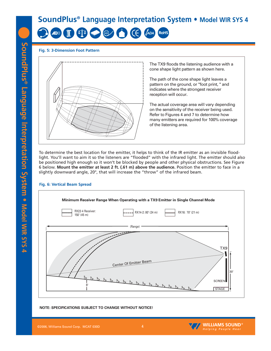
SoundPlus | Fig. 5: |
|
| |
| The TX9 floods the listening audience with a | |||
| cone shape light pattern as shown here. | |||
| The path of the cone shape light leaves a | |||
® |
| pattern on the ground, or "foot print, " and | ||
Language |
| |||
| indicates where the strongest receiver | |||
| reception will occur. | |||
| The actual coverage area will vary depending | |||
| on the sensitivity of the receiver being used. | |||
| Refer to Figures 4 and 7 to determine how | |||
| many emitters are required for 100% coverage | |||
Interpretation |
| |||
| of the listening area. | |||
To determine the best location for the emitter, it helps to think of the IR emitter as an invisible flood- | ||||
light. You’ll want to aim it so the listeners are “flooded” with the infrared light. The emitter should also | ||||
be positioned high enough so it won’t be blocked by people and other physical obstructions. See Figure | ||||
6 below. Mount the emitter at least 2 ft. (.61 m) above the audience. Position the emitter to face in a | ||||
System • | slightly downward angle, 20°, that will increase the “throw” of the infrared beam. | |||
Fig. 6: Vertical Beam Spread |
|
| ||
Minimum Receiver Range When Operating with a TX9 Emitter in Single Channel Mode | ||||
Model | RX16: 70' (21 m) | |||
150' (45 m) | ||||
|
| |||
|
|
| ||
WIR SYS |
| (Range) |
| |
|
| TX9 | ||
4 |
|
| ||
|
|
| ||
|
|
| 30' | |
|
|
| SCREEN | |
| 6' |
|
| |
|
|
| STAGE | |
NOTE: SPECIFICATIONS SUBJECT TO CHANGE WITHOUT NOTICE!
| ©2006, Williams Sound Corp. MCAT 030D | 4 |
|
|
|