SoundPlus® Language Interpretation System • Model WIR SYS 4
SoundPlus® Language Interpretation System • Model WIR SYS 4
![]() D
D![]()
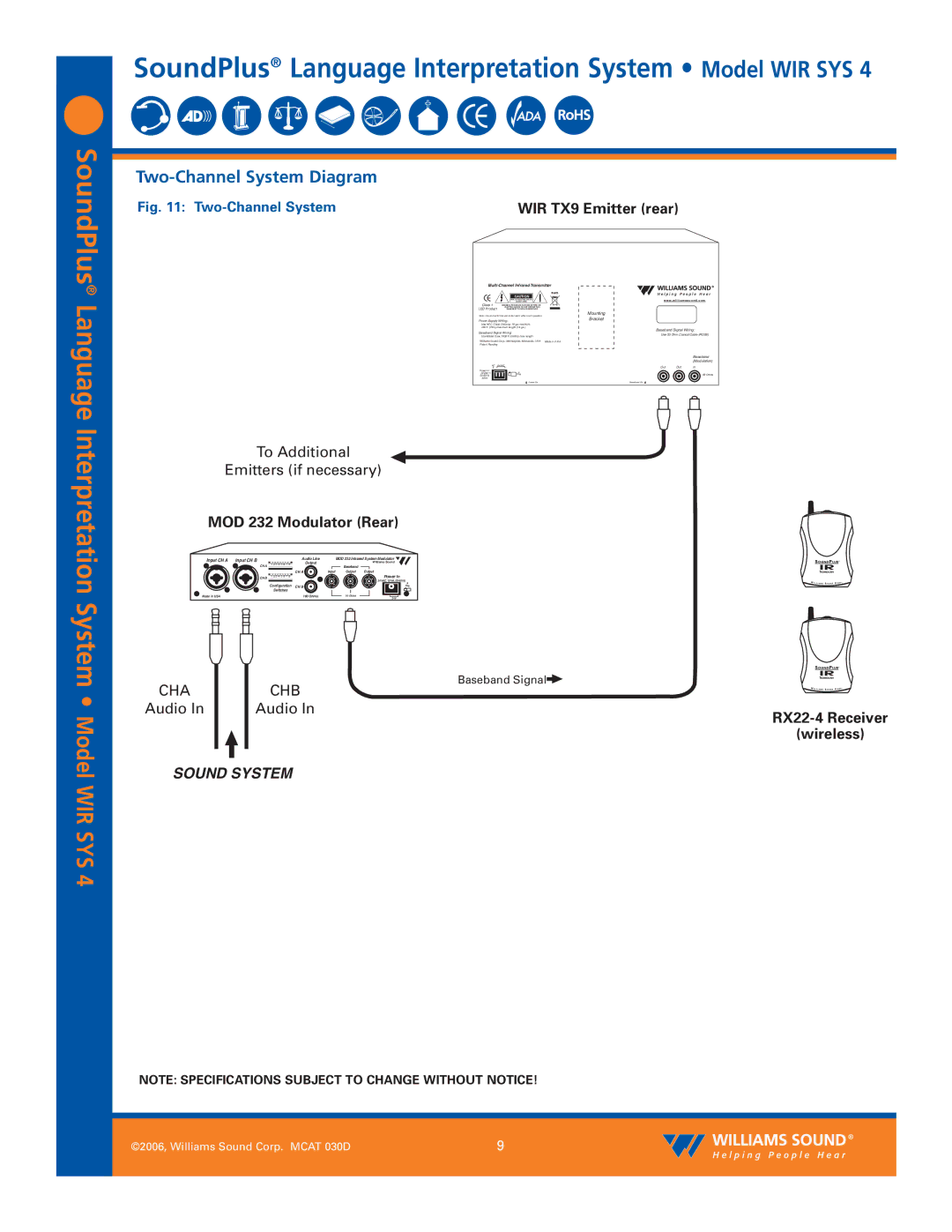
Two-Channel System Diagram
Fig. 11: |
|
|
| WIR TX9 Emitter (rear) |
|
| |||||||||
|
|
|
|
|
|
|
|
|
|
|
|
|
|
| |
|
|
|
|
| |||||||||||
|
|
|
|
|
|
|
|
|
| RoHS |
|
|
| ||
|
|
|
|
| CAUTION |
|
|
|
|
|
|
|
|
| |
|
|
|
|
| RISK OF ELECTRIC SHOCK |
|
|
|
|
| w w w . w i l l i a m s s o u n d . c o m | ||||
|
|
|
|
| DO NOT OPEN |
|
|
|
|
| |||||
| Class 1 | ELECTRIC SHOCK DO NOT EXPOSE THIS |
|
|
|
|
|
|
| ||||||
|
|
| WARNING: TO REDUCE THE RISK OF FIRE OR |
|
|
|
|
|
|
| |||||
| LED Product |
| EQUIPMENT TO RAIN OR MOISTURE. |
|
| Mounting |
|
|
| ||||||
| Note: It is normal for this unit to feel warm while it is in operation. |
|
|
|
|
| |||||||||
| Power Supply Wiring: |
|
| Bracket |
|
|
| ||||||||
| Use NEC, Class 2 Wiring, 18 ga. minimum, |
|
|
|
|
|
|
| |||||||
| 200 ft. (70m) maximum length (18 ga.) |
|
| Baseband Signal Wiring: | |||||||||||
| Baseband Signal Wiring: |
|
| ||||||||||||
|
|
|
| Use 50 Ohm Coaxial Cable (RG58) | |||||||||||
| Use RG58 Coax,1000 ft. (350m) max. length |
|
|
|
|
|
|
| |||||||
| Williams Sound Corp., Minneapolis, Minnesota, USA | Made in U.S.A. |
|
|
| ||||||||||
| Patent Pending |
|
|
|
|
|
|
|
|
|
|
|
|
| |
|
|
|
|
|
|
|
|
|
|
|
|
|
| Baseband | |
|
|
|
|
|
|
|
|
|
|
|
|
|
| (Modulation) | |
| NC | 24 VAC |
|
|
| Out | Out | In | |||||||
| Power In: |
|
|
|
|
|
|
|
|
|
| ||||
| 24VAC~ |
|
|
|
| Plug |
|
|
|
|
|
| 50 Ohms | ||
|
|
|
|
|
|
|
|
|
|
|
|
|
|
| |
| 35VA |
|
|
|
|
|
|
|
|
|
|
|
|
|
|
|
|
|
|
|
| Power On |
|
| Baseband On |
|
|
| |||
|
|
|
|
|
|
|
|
|
|
|
|
|
|
|
|
|
|
|
|
|
|
|
|
|
|
|
|
|
|
|
|
To Additional
Emitters (if necessary)
MOD 232 Modulator (Rear)
Input CH A | Input CH B |
| Audio Line |
| MOD 232 Infrared System Modulator | |
1 2 3 4 5 6 7 8 | Output |
|
| Williams Sound | ||
| CH A |
| Baseband |
| ||
|
|
|
|
| ||
|
|
| CH A | Input | Output | Output |
| CH B 1 2 3 4 5 6 7 8 |
|
|
| Power In | |
|
| Configuration | CH B |
|
| 24 VAC, 15 VA, |
|
|
|
| Plug | ||
|
| Switches |
|
|
|
|
Made in USA |
|
| 100 Ohms |
| 50 Ohms | 24V |
|
|
|
|
|
| |
CHA | CHB | Baseband Signal |
| ||
Audio In | Audio In | |
|
|
(wireless)
SOUND SYSTEM
NOTE: SPECIFICATIONS SUBJECT TO CHANGE WITHOUT NOTICE!
| ©2006, Williams Sound Corp. MCAT 030D | 9 |
|
|
|