ANTENNA MOUNTING INSTRUCTIONS
STEP 1: Attach mounting bracket to bottom of antenna as shown in Figure 1 and mount antenna on mast. The tab on the plastic screw and notch on the bracket ensure a secure connection. Use center set of holes on bracket. Tighten
FIGURE 1
(NON-AMPLIFIED)
STEP 2. Attach downlead from antenna to TV set.
(AMPLIFIED MODELS) If using the power supply, follow these steps.
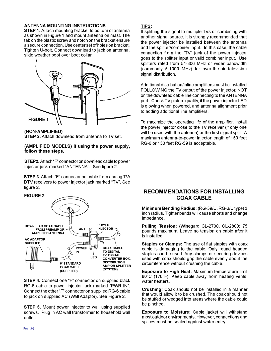
STEP2. Attach “F” connector on downlead cable to power injector jack marked “ANTENNA”. See figure 2.
STEP 3. Attach “F” connector on cable from analog TV/ DTV receivers to power injector jack marked “TV”. See figure 2.
TIPS:
If splitting the signal to multiple TVs or combining with another signal source, it is strongly recommended that the power injector be installed between the antenna and the splitter/combiner input. In this case, the cable connection from the “TV” jack of the power injector goes to the splitter input or valid combiner input. Use splitters rated from
Additional distribution/inline amplifiers must be installed FOLLOWING the TV output of the power injector, NOT on the downlead cable line connecting to the ANTENNA port. Check TV picture quality, if the power injector LED is glowing when powered, and antenna alignment prior to adding additional line amplifiers.
To maximize the operating life of the amplifier, install the power injector close to the TV receiver (if only one will be used with the antenna) or the first signal split. A maximum
RECOMMENDATIONS FOR INSTALLING
FIGURE 2
DOWNLEAD COAX CABLE | ANT. |
FROM PREAMP OR | |
AMPLIFIED ANTENNA |
|
AC ADAPTOR |
|
SUPPLIED |
|
| POWER |
| IN |
6’ STANDARD COAX CABLE (SUPPLIED)
POWER
INJECTOR ![]()
TV
COAX CABLE TO DIGITAL TV, DIGITAL
LED CONVERTER BOX, DISTRIBUTION AMP OR SPLITTER (SYSTEM)
COAX CABLE
Minimum Bending Radius:
Pulling Tension: (Winegard
Staples or Clamps: The use of flat staples with coax cable is damaging to the cable. Only round headed staples can be used. Any clamps or securing devices used with coax should grip the cable evenly about the circumference without crushing the cable.
Exposure to High Heat: Maximum temperature limit 80°C (176°F). Keep cable away from heating vents,
STEP 4. Connect one “F” connector on supplied black
STEP 5. Mount power injector to wall using supplied screws. Plug in AC wall transformer to household wall outlet.
water heaters.
Crushing: Coax should not be installed in a manner that would allow it to be crushed. The coax should not be stuffed or wedged into areas where the cable could be pinched.
Exposure to Moisture: Cable jacket will withstand most outdoor environments. However, connections and splices must be sealed against water entry.
Rev. 1/09