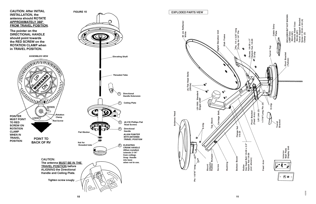
CAUTION: After initial | FIGURE 15 |
installation, the |
|
antenna should rotate |
|
approximately 360° |
|
from travel position. |
|
The pointer on the |
|
directional handle |
|
should point towards |
|
the RED SCREW on the |
|
ROTATION CLAMP when |
|
in TRAVEL POSITION. |
|
ASSEMBLED VIEW | Elevating Shaft |
Threaded Tube
EXPLODED PARTS VIEW
46 cm Reflector White | Digital Elevation Unit | Dish Frame | Pin, 1/4 x 3.25” long | Screw, | Turret Top Cable Entry Plate | INCLUDED BUT NOT SHOWN LNBF Coax | |
Pivot Bracket (Tubes) | |||||||
Flat Head Bolts | (White) |
|
|
|
|
|
|
POINTER MUST POINT TO RED SCREW ON ROTATION CLAMP WHEN IN TRAVEL POSITION
|
| 3 | Directional |
|
|
| Handle Extension |
|
| 1 | Ceiling Plate |
Rotation |
|
|
|
Clamp |
|
|
|
Red Screw |
| 2 (4) #10 Phillips Flat | |
|
| ||
|
|
| Head Screws |
|
| 4 | Directional |
| Flat Washer |
| Handle |
|
| ALIGN POINTER | |
|
|
| |
POINT TO |
|
| WITH ANTENNA |
|
| TRAVEL POSITION | |
BACK OF RV | Nut for |
|
|
| threaded tube | 5 | ELEVATING |
|
|
| CRANK HANDLE |
|
|
| (When installed, |
|
|
| extends |
|
|
| from ceiling). |
CAUTION: |
|
| Snap Handle |
|
| into base | |
The antenna MUST BE IN THE |
| when not in use. | |
TRAVEL POSITION before |
|
|
|
ALIGNING the Directional |
|
|
|
Handle and Ceiling Plate. |
|
|
|
Tighten screw snugly 

(4) |
|
|
|
|
|
|
|
|
| |
Antenna Head | Top Boom | Carriage Bolt |
| Nut | Pivot Bracket (Feed Arm) | Lift Link (2) | Travel Bracket | |||
|
|
|
|
| Flange |
|
|
|
|
|
9/16”long |
| RubberBumper | Screw | Bushing | Bottom Boom | Roller Hex Head Bolt |
| Feed Arm |
| Interior Wall Plate Display Unit |
| Mount Adapter |
|
| |||||||
Pin 1- |
|
|
|
|
|
|
|
|
|
|
10 | 11 |
4/22/02