TROUBLE SHOOTING
NO PICTURE ON TV
1.Do you have a clear line of sight to the satellite? Are
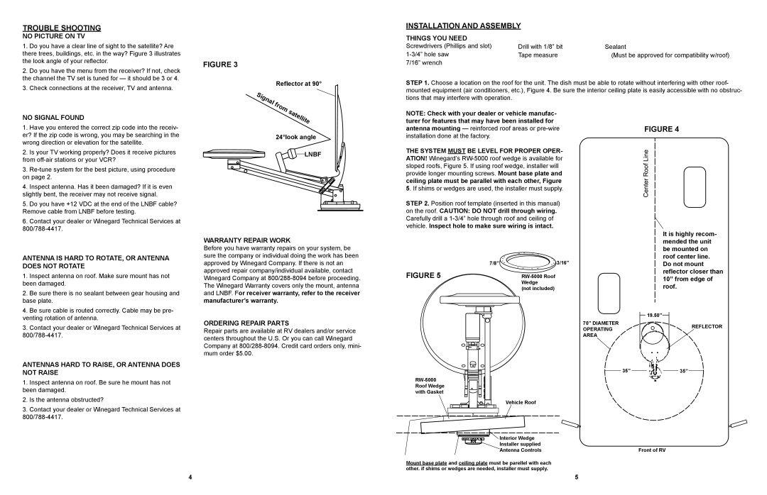
there trees, buildings, etc. in the way? Figure 3 illustrates the look angle of your reflector.
2.Do you have the menu from the receiver? If not, check the channel the TV set is tuned for — it should be 3 or 4.
3.Check connections at the receiver, TV and antenna.
FIGURE 3
Reflector at 90°
INSTALLATION AND ASSEMBLY
THINGS YOU NEED
Screwdrivers (Phillips and slot) | Drill with 1/8” bit | Sealant |
Tape measure | (Must be approved for compatibility w/roof) | |
7/16” wrench |
|
|
STEP 1. Choose a location on the roof for the unit. The dish must be able to rotate without interfering with other roof- mounted equipment (air conditioners, etc.), Figure 4. Be sure the interior ceiling plate is easily accessible with no obstruc- tions that may interfere with operation.
NO SIGNAL FOUND
1. | Have you entered the correct zip code into the receiv- |
er? If the zip code is wrong, you may be searching in the | |
wrong direction or elevation for the satellite. | |
2. | Is your TV working properly? Does it receive pictures |
from | |
3. | |
on page 2. | |
4. | Inspect antenna. Has it been damaged? If it is even |
slightly bent, the receiver may not receive signal. | |
5. | Do you have +12 VDC at the end of the LNBF cable? |
Remove cable from LNBF before testing. | |
6. | Contact your dealer or Winegard Technical Services at |
24°look angle
LNBF
NOTE: Check with your dealer or vehicle manufac- turer for features that may have been installed for antenna mounting — reinforced roof areas or
THE SYSTEM MUST BE LEVEL FOR PROPER OPER- ATION! Winegard’s
STEP 2. Position roof template (inserted in this manual) on the roof. CAUTION: DO NOT drill through wiring. Carefully drill a
FIGURE 4
ANTENNA IS HARD TO ROTATE, OR ANTENNA DOES NOT ROTATE
1.Inspect antenna on roof. Make sure mount has not been damaged.
2.Be sure there is no sealant between gear housing and base plate.
4.Be sure cable is routed correctly. Cable may be pre- venting rotation of antenna.
3.Contact your dealer or Winegard Technical Services at
ANTENNAS HARD TO RAISE, OR ANTENNA DOES NOT RAISE
1.Inspect antenna on roof. Be sure he mount has not been damaged.
2.Is the antenna obstructed?
3.Contact your dealer or Winegard Technical Services at
WARRANTY REPAIR WORK
Before you have warranty repairs on your system, be sure the company or individual doing the work has been approved by Winegard Company. If there is not an approved repair company/individual available, contact Winegard Company at
ORDERING REPAIR PARTS
Repair parts are available at RV dealers and/or service centers throughout the U.S. Or you can call Winegard Company at
FIGURE 5
7/8” ![]()
![]()
![]()
![]()
![]() 3/16”
3/16”
(not included)
70” DIAMETER OPERATING AREA
35”
Vehicle Roof
It is highly recom- mended the unit be mounted on roof center line. Do not mount reflector closer than 10” from edge of roof.
19.50”
REFLECTOR
35”
Interior Wedge |
Installer supplied |
Antenna Controls | Front of RV |
Mount base plate and ceiling plate must be parellel with each other. if shims or wedges are needed, installer must supply.
4 | 5 |
