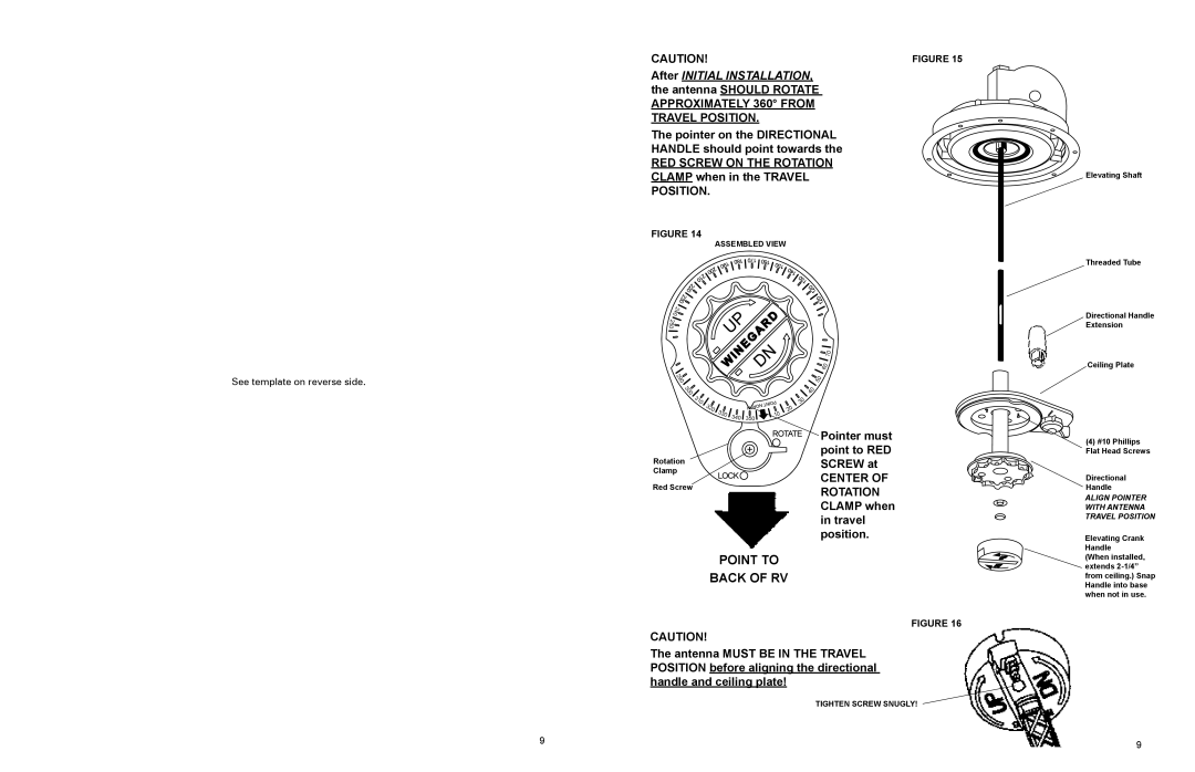
CAUTION! | FIGURE 15 |
After INITIAL INSTALLATION, |
|
the antenna SHOULD ROTATE |
|
APPROXIMATELY 360° FROM |
|
TRAVEL POSITION. |
|
The pointer on the DIRECTIONAL |
|
HANDLE should point towards the |
|
RED SCREW ON THE ROTATION |
|
CLAMP when in the TRAVEL |
|
POSITION. |
|
FIGURE 14 |
|
ASSEMBLED VIEW |
|
Elevating Shaft
Threaded Tube
See template on reverse side.
240![]()
![]()
![]()
250
290
300 |
|
|
|
310 | 320 |
|
|
| 330 |
| |
|
| 340 | |
|
|
|
NORTH ![]() 350
350![]()
POINT ![]()
![]() 10
10
20
![]()
![]() 70
70 ![]()
![]()
![]() 60
60
![]()
![]() 50
50
![]()
![]() 40
40
30
Directional Handle Extension
Ceiling Plate
Pointer must point to RED
Rotation | SCREW at | |
Clamp | ||
CENTER OF | ||
Red Screw | ||
ROTATION | ||
| ||
| CLAMP when | |
| in travel | |
| position. |
POINT TO
BACK OF RV
FIGURE 16
CAUTION!
The antenna MUST BE IN THE TRAVEL POSITION before aligning the directional handle and ceiling plate!
TIGHTEN SCREW SNUGLY!
(4)#10 Phillips Flat Head Screws
Directional
Handle
ALIGN POINTER WITH ANTENNA TRAVEL POSITION
Elevating Crank Handle (When installed, extends
9 | 9 |
|
