Installing the Replacement LNB Assembly
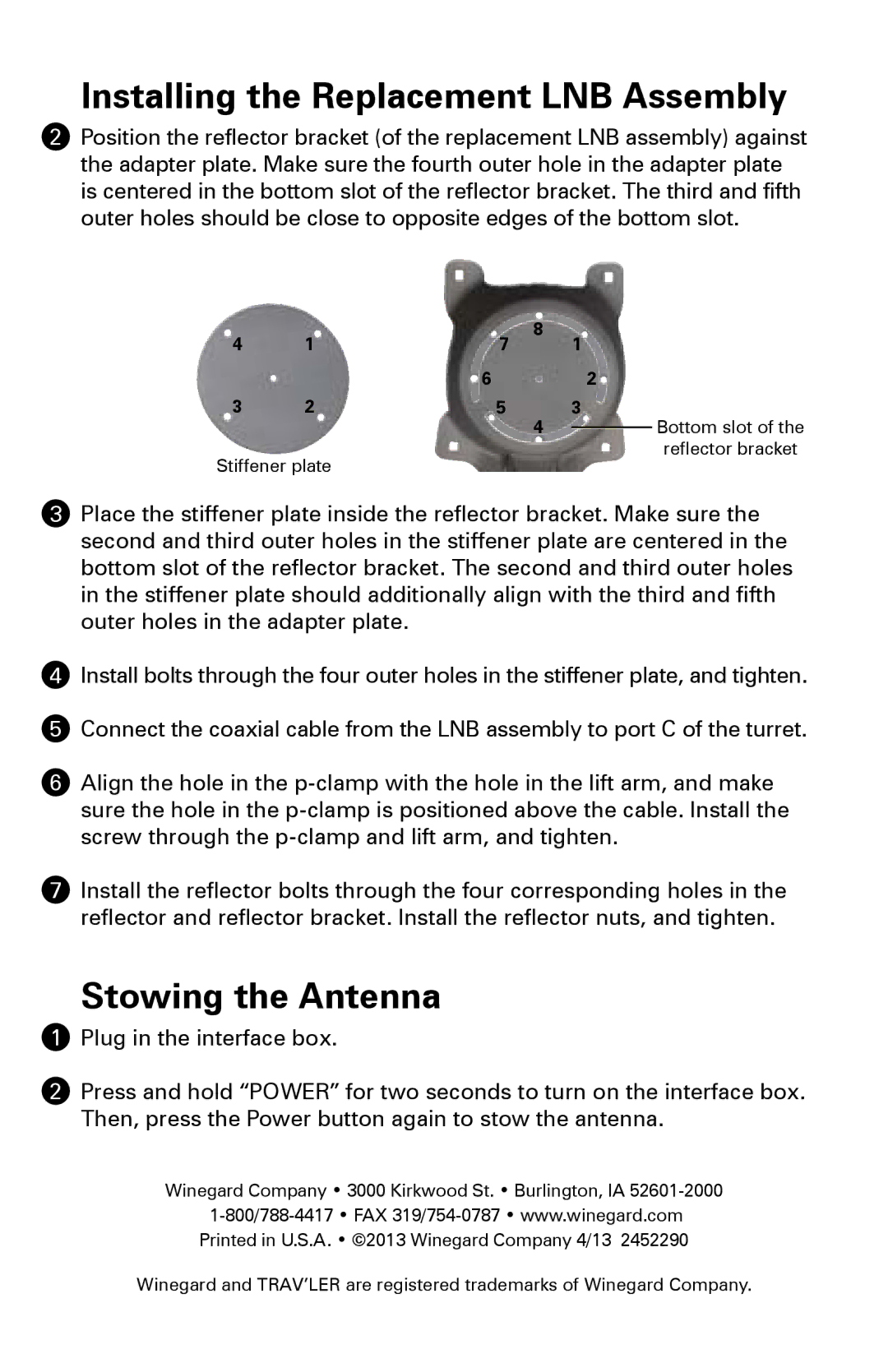
2Position the reflector bracket (of the replacement LNB assembly) against the adapter plate. Make sure the fourth outer hole in the adapter plate is centered in the bottom slot of the reflector bracket. The third and fifth outer holes should be close to opposite edges of the bottom slot.
4 | 1 | 7 | 8 | 1 |
|
|
|
|
| ||||
|
| 6 |
| 2 |
|
|
3 | 2 | 5 | 4 | 3 |
| Bottom slot of the |
|
|
|
|
| ||
|
|
|
|
|
reflector bracket
Stiffener plate
3Place the stiffener plate inside the reflector bracket. Make sure the second and third outer holes in the stiffener plate are centered in the bottom slot of the reflector bracket. The second and third outer holes in the stiffener plate should additionally align with the third and fifth outer holes in the adapter plate.
4Install bolts through the four outer holes in the stiffener plate, and tighten.
5Connect the coaxial cable from the LNB assembly to port C of the turret.
6Align the hole in the
7Install the reflector bolts through the four corresponding holes in the reflector and reflector bracket. Install the reflector nuts, and tighten.
Stowing the Antenna
1Plug in the interface box.
2Press and hold “POWER” for two seconds to turn on the interface box. Then, press the Power button again to stow the antenna.
Winegard Company • 3000 Kirkwood St. • Burlington, IA
Printed in U.S.A. • ©2013 Winegard Company 4/13 2452290
Winegard and TRAV’LER are registered trademarks of Winegard Company.
