CONNECTING POWER SUPPLY
1.Select location for power supply. Run two coax cables (three if Set 2 jack is going to be used)
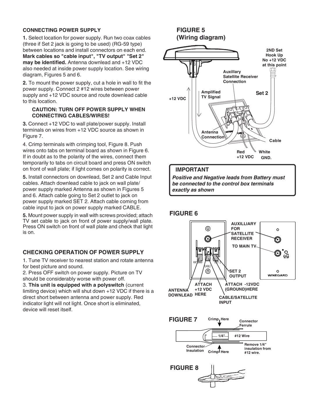
Mark cables so "cable input", "TV output" "Set 2" may be identified. Antenna downlead and +12 VDC also needed at inside power supply location. See wiring diagram, Figures 5 and 6.
2.To mount the power supply, cut a hole in wall to fit the power supply. Connect 2 #12 wires between power supply and +12 VDC source and route downlead cable to this location.
CAUTION: TURN OFF POWER SUPPLY WHEN CONNECTING CABLES/WIRES!
3.Connect +12 VDC to wall plate/power supply. Install terminals on wires from +12 VDC source as shown in Figure 7.
4.Crimp terminals with crimping tool, Figure 8. Push wires onto tabs on terminal board as shown in Figure 6. If in doubt as to the polarity of the wires, connect them temporarily to tabs on circuit board and press ON switch on front of wall plate; if light comes on polarity is correct.
5.Install connectors on downlead, Set 2 and Cable Input cables. Attach downlead cable to jack on wall plate/ power supply marked Antenna as shown in Figures 5 and 6. Attach cable going to Set 2 outlet to jack on power supply marked SET 2. Attach cable coming from cable input to jack on power supply marked CABLE.
5.Mount power supply in wall with screws provided; attach TV set cable to jack on front of power supply/wall plate. Press ON switch on front of wall plate and check that light is on.
CHECKING OPERATION OF POWER SUPPLY
1.Tune TV receiver to nearest station and rotate antenna for best picture and sound.
2.Press OFF switch on power supply. Picture on TV should be considerably worse with power off.
3.This unit is equipped with a polyswitch (current limiting device) which will shut down +12 VDC if there is a direct short between antenna and power supply. Red indicator light will not light. Once short is eliminated, device will reset itself.
FIGURE 5 (Wiring diagram)
2ND Set
Hook Up
No +12 VDC at this point
Auxillary
Satellite Receiver
Connection
| Amplified | Set 2 |
+12 VDC | TV Signal |
|
|
|
Antenna
Connection
Cable
Red White +12 VDC GND.
IMPORTANT
Positive and Negative leads from Battery must be connected to the control box terminals exactly as shown
FIGURE 6
AUXILLIARY
FOR
SATELLITE
RECEIVER
TO MAIN TV
SET 2
OUTPUT
ATTACH ATTACH
ANTENNA +12 VDC (GROUND)HERE
DOWNLEAD HERE
CABLE/SATELLITE INPUT
FIGURE 7 Crimp Here Connector Ferrule
|
|
| 1/4" |
|
| #12 Wire | ||
|
|
| ||||||
Connector |
|
|
|
|
|
|
| Remove 1/4" |
|
|
|
|
|
|
| ||
|
|
|
|
|
|
| insulation from | |
Insulation | Crimp Here |
| ||||||
| #12 wire. | |||||||
|
| |||||||
FIGURE 8
3