W O L F PRO VENTILATION HOOD U S E & C A R E
R E C E S S E D CONTROLS | HEAT SENTRY F E AT U R E | |
Controls for Pro ventilation hoods and hood | Heat Sentry feature turns the ventilation hood | |
liners are recessed under the front edge of the | on when heat is sensed and adjusts the blower | |
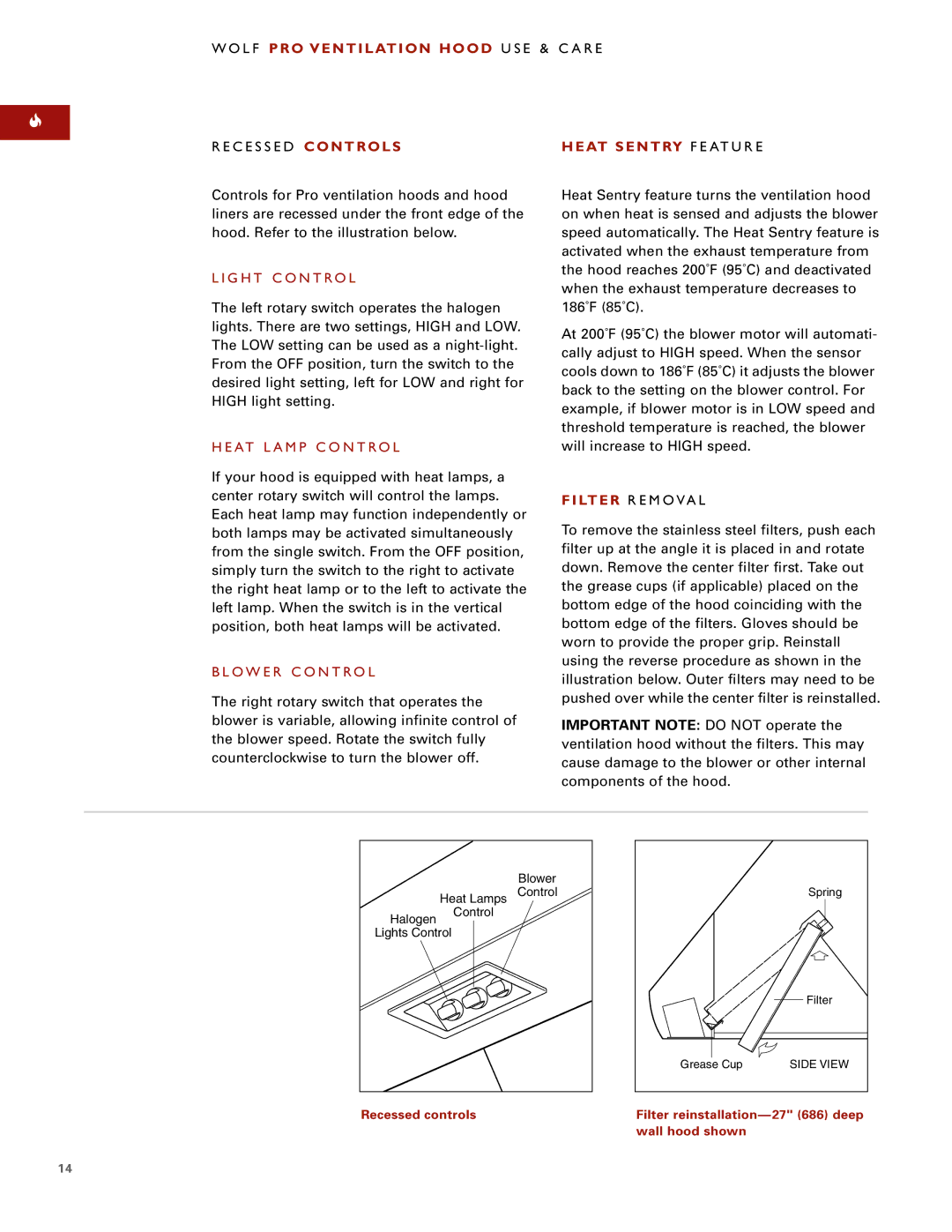
hood. Refer to the illustration below. | speed automatically. The Heat Sentry feature is | |
| activated when the exhaust temperature from | |
L I G H T C O N T RO L | the hood reaches 200˚F (95˚C) and deactivated | |
when the exhaust temperature decreases to | ||
| ||
The left rotary switch operates the halogen | 186˚F (85˚C). | |
lights. There are two settings, HIGH and LOW. | At 200˚F (95˚C) the blower motor will automati- | |
The LOW setting can be used as a | ||
cally adjust to HIGH speed. When the sensor | ||
From the OFF position, turn the switch to the | ||
cools down to 186˚F (85˚C) it adjusts the blower | ||
desired light setting, left for LOW and right for | ||
back to the setting on the blower control. For | ||
HIGH light setting. | ||
example, if blower motor is in LOW speed and | ||
| ||
| threshold temperature is reached, the blower | |
H E AT L A M P C O N T R O L | will increase to HIGH speed. | |
If your hood is equipped with heat lamps, a |
| |
center rotary switch will control the lamps. | FILTER R E M O VA L | |
Each heat lamp may function independently or | ||
To remove the stainless steel filters, push each | ||
both lamps may be activated simultaneously | ||
from the single switch. From the OFF position, | filter up at the angle it is placed in and rotate | |
simply turn the switch to the right to activate | down. Remove the center filter first. Take out | |
the right heat lamp or to the left to activate the | the grease cups (if applicable) placed on the | |
left lamp. When the switch is in the vertical | bottom edge of the hood coinciding with the | |
position, both heat lamps will be activated. | bottom edge of the filters. Gloves should be | |
| worn to provide the proper grip. Reinstall | |
B L O W E R C O N T RO L | using the reverse procedure as shown in the | |
illustration below. Outer filters may need to be | ||
| ||
The right rotary switch that operates the | pushed over while the center filter is reinstalled. | |
blower is variable, allowing infinite control of | IMPORTANT NOTE: DO NOT operate the | |
the blower speed. Rotate the switch fully | ||
ventilation hood without the filters. This may | ||
counterclockwise to turn the blower off. | ||
cause damage to the blower or other internal | ||
| ||
| components of the hood. |
|
| Blower |
| Heat Lamps | Control |
Halogen | Control |
|
|
| |
Lights Control |
| |
Recessed controls
| Spring |
| Filter |
Grease Cup | SIDE VIEW |
Filter reinstallation—27" (686) deep wall hood shown
14
