42C-6 specifications
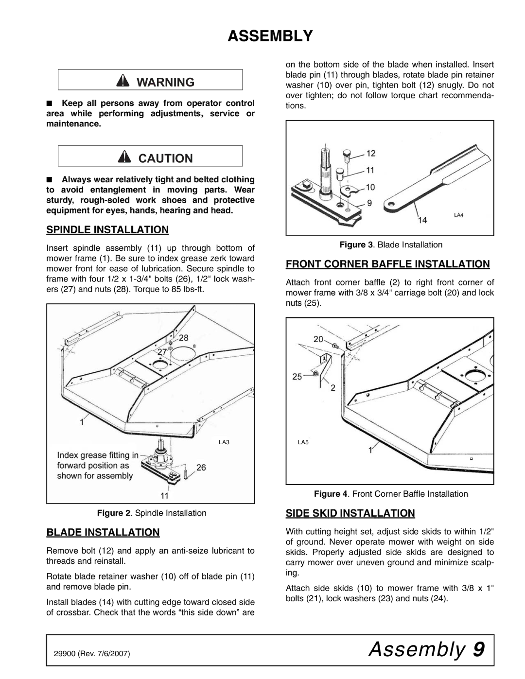
Woods Equipment has a long-standing reputation for producing high-quality agricultural implements and attachments, and the 42C-6 is a standout in their lineup. Designed primarily for compact utility tractors, this rotary cutter is engineered to offer reliable performance, durability, and ease of use for both commercial and residential applications.One of the main features of the Woods 42C-6 is its cutting width of 42 inches, making it an ideal choice for maneuvering in tight spaces without sacrificing productivity. It is equipped with a heavy-duty steel deck that provides exceptional strength and durability, allowing it to handle tough brush and grass with ease. The cutter incorporates reinforced sidebands and a robust frame, ensuring a long lifespan even under rigorous conditions.
The 42C-6 showcases advanced cutting technology with its high-speed blade rotation. This feature enhances the efficiency of grass and brush cutting, delivering a clean and precise cut. Additionally, the blades are designed to be easily replaceable, which simplifies maintenance and reduces downtime for operators.
Another notable characteristic is the adjustable hitch. The Woods 42C-6 offers a universal mount that allows compatibility with a wide range of tractor models. This flexibility makes it an attractive choice for farm owners and landscaping businesses seeking to maximize their equipment's versatility.
Safety is a priority in the design of the 42C-6. It is equipped with a safety guard that minimizes the risk of debris being flung from the cutter, ensuring a safer working environment. The cutter also features a slip clutch that protects the driveline from overload, further enhancing its reliability during operation.
Ease of operation is another significant advantage of the Woods 42C-6. With a straightforward attachment process, operators can quickly connect and disconnect the cutter, saving valuable time during job transitions. The cutter's lightweight design further enhances maneuverability, allowing users to navigate around obstacles with confidence.
In summary, the Woods Equipment 42C-6 rotary cutter combines durability, efficiency, and safety in a compact package designed for various cutting needs. With its robust construction, ease of use, and reliable performance, it is well-suited for those looking to tackle tough mowing jobs in a variety of settings. Whether for agricultural use or landscaping projects, the 42C-6 stands as a testament to Woods Equipment's commitment to quality and innovation in outdoor equipment.

