SCREW TERMINALS
O - Infrared Output - Positive terminal for the IR output signal.
G - Ground - Negative terminal for the IR output signal.
The "O" and "G" terminals drive IR emitters directly or the IR input of Xantech connecting blocks, IR routers, interface modules, etc.
12VDC - 12 volts output, positive & negative terminals.
INPUTS
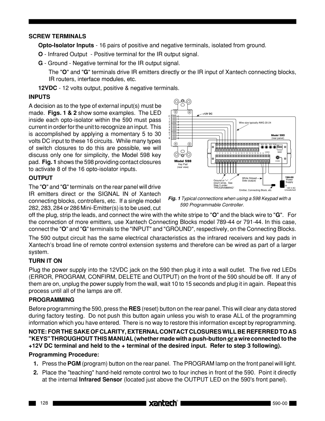
A decision as to the type of external input(s) must be made. Figs. 1 & 2 show some examples. The LED inside each
C![]() C
C
1 ![]() 1
1
2 ![]() 2
2
3 ![]() 3
3
4 ![]() 4
4
5 ![]() 5
5
6 ![]() 6
6
7 ![]() 7
7
8 ![]() 8
8
Model 598
Key Pad
(rear view)
+12V DC
|
|
|
|
|
|
|
| Wire size typically AWG | |||
|
|
|
|
|
|
|
|
|
|
| Model 590 |
|
|
|
|
|
|
|
|
|
|
| (rear panel) |
|
|
|
|
|
|
|
|
|
| RES DEL SEQ PGM ON | |
+ |
|
|
|
|
|
|
|
|
| 12VDC | 1 2 3 4 |
1 | 2 | 3 | 4 | 5 | 6 | 7 | 8 | 9 | 10 11 12 13 14 15 16 | BANK | |
O G – + |
| ||||||||||
12VDC |
– |
OUTPUT
The "O" and "G" terminals on the rear panel will drive IR emitters direct or the SIGNAL IN of Xantech
connecting blocks, controllers, etc. If a single model 282, 283, 284 or 286
off the plug, strip the leads, and connect the wire with the white stripe to "O" and the black wire to "G". For the connection of more emitters, use Xantech Connecting Blocks model
The 590 output circuit has the same electrical characteristics as the infrared receivers and key pads in Xantech’s broad line of remote control extension systems and therefore can be wired as part of a larger system.
TURN IT ON
Plug the power supply into the 12VDC jack on the 590 then plug it into a wall outlet. The five red LEDs (ERROR, PROGRAM, CONFIRM, DELETE and OUTPUT) on the front of the 590 should be off. If any of them are on, unplug the power supply from the wall, wait 10 to 15 seconds and plug it in again. Repeat this process until all of the lamps are off.
PROGRAMMING
Before programming the 590, press the RES (reset) button on the rear panel. This will clear any data stored during factory testing. Do not push this button again unless you wish to erase ALL of the programming information which you have entered. There is no way to restore this information except by reprogramming.
NOTE: FOR THE SAKE OF CLARITY, EXTERNAL CONTACT CLOSURES WILL BE REFERRED TO AS "KEYS" THROUGHOUT THIS MANUAL (whether made with a
Programming Procedure:
1.Press the PGM (program) button on the rear panel. The PROGRAM lamp on the front panel will light.
2.Place the "teaching"
128