A sequence is completed. You may now test it by pressing the ON/OFF key (bank 1). It should now send the three commands to turn the AM/FM receiver ON, turn the VCR ON and select the VCR Input on the receiver, in that order.
USING THE 590 PROGRAMMABLE CONTROLLER WITH NON- MOMENTARY INPUTS
The Model 590 was designed to be used with momentary contact switches. In such applications, a button is pressed, the 590 generates an IR command, and the button is released. If the button is not released, the 590 will either continue to repeat the same IR command or send no signal at all after the initial burst. As long as one key is pressed, subsequent actions will be locked out; the other keys (inputs) will not respond.
Sometimes it is desirable to have an IR command generated in response to some change or action to trigger automated functions in an audio/video system.
•For example, if an AM/FM receiver is turned ON manually, an IR command sequence can be made to turn a TV set ON and set the channel to 4 at the same time.
•When the AM/FM receiver is turned OFF manually, an IR command can also turn the TV set OFF.
120 V AC |
|
|
|
|
|
|
|
|
|
|
|
|
|
From a |
|
|
|
|
| 599 |
|
|
|
|
|
|
|
Switched | + |
|
|
| IN+ |
|
|
| OFF |
|
|
| |
Source | – |
|
|
| PULSED |
|
|
|
|
|
| ||
|
|
| IN– |
|
|
| ON |
|
|
| |||
|
|
|
|
| SWITCHING |
|
|
|
| ||||
Model 781C or |
|
|
| GND |
| GND |
|
|
| ||||
|
|
| MODULE |
|
|
|
|
|
| ||||
any 5 to 30 V DC |
|
|
| +12V |
|
|
|
| +12V |
|
|
| |
Power Supply |
|
|
|
|
|
|
|
|
|
|
| ||
|
|
|
|
| ® |
|
|
|
|
|
| +12V DC | |
will work |
|
|
|
|
|
|
|
|
|
|
| ||
|
|
|
|
| SYLMAR, CA • MADE IN U.S.A. |
|
|
| |||||
|
|
|
|
|
|
|
|
|
|
|
|
| Model 590 |
|
|
|
|
|
|
|
|
|
|
|
|
| (rear panel) |
|
|
|
|
|
|
|
|
|
|
| RES DEL SEQ PGM ON | ||
| + |
|
|
|
|
|
|
|
|
|
| 12VDC | 1 2 3 4 |
| 1 | 2 | 3 | 4 | 5 6 | 7 8 9 10 11 | 12 | 13 | 14 | 15 16 | O G | BANK | |
| – + |
| |||||||||||
12VDC |
– |
Momentary |
|
Switches for | Ground or |
other system devices | return wires. |
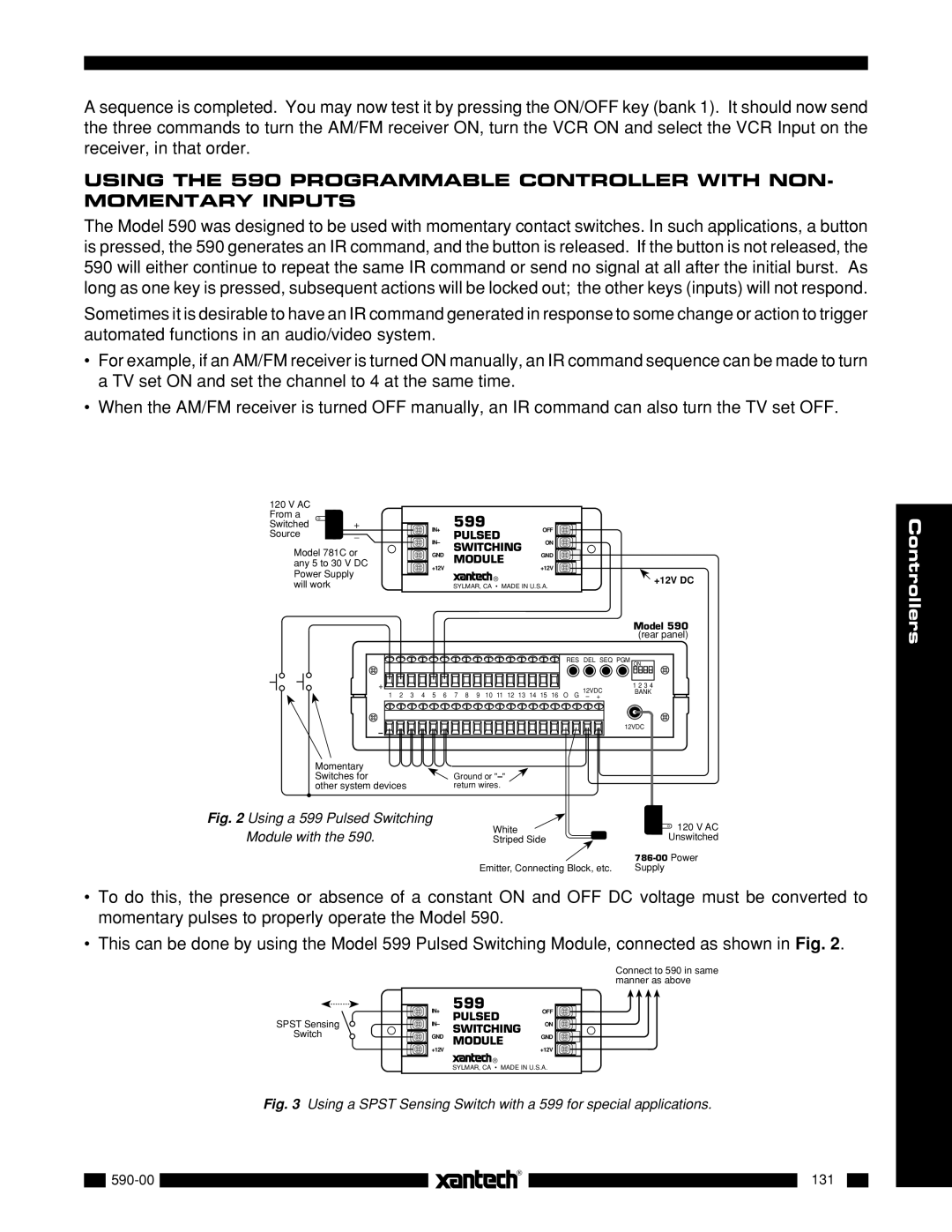
Fig. 2 Using a 599 Pulsed Switching | White |
|
| 120 V AC |
Module with the 590. |
|
| ||
Striped Side |
|
| Unswitched | |
|
| |||
| Emitter, Connecting Block, etc. | Supply | ||
•To do this, the presence or absence of a constant ON and OFF DC voltage must be converted to momentary pulses to properly operate the Model 590.
•This can be done by using the Model 599 Pulsed Switching Module, connected as shown in Fig. 2.
Connect to 590 in same manner as above
| IN+ | 599 | OFF | |
| PULSED | |||
SPST Sensing | IN– | ON | ||
SWITCHING | ||||
Switch | GND | GND | ||
MODULE | ||||
| +12V |
| +12V |
®
SYLMAR, CA • MADE IN U.S.A.
Fig. 3 Using a SPST Sensing Switch with a 599 for special applications.
|
|
| |
|
|
|
|
|
|
| 131 |
| |
|
|
|
| |||
|
|
|
|
|
|
|
|
|
|
|
|
|
|
Controllers