3. | A high current power supply, the |
| VDC), provides the additional current needed for |
| the keypads. |
4. | A |
| AC outlet on the A/V receiver, is used as a source |
| of system power ON/OFF STATUS voltage (12 |
| VDC) for the Smart Pad2s and the |
| Receiver. |
5. | A resistor (1k to 10k Ohm) may be added in series |
| with the STATUS line, if desired, to adjust the |
| brightness of the STATUS LED in the |
| Receiver. Refer to "REMOTE ROOM 3", Fig. 5. |
Hand Held
Remote
781RG
Power Supply
To 120 V AC (unswitched)
OUTPWR | IR | VGS |
RCVR |
CB12 Connecting Block (Included with the
Conductor
Cable
Cable
Modules
6. | As with the previous example, an RC68 is used to |
| teach learning remotes (used with the IR receiv- |
| ers) the commands for each of the DC4 players. |
7. | An RC68 and the Xantech Dragon DropIR™ |
| software are used to program the Smart Pad2 |
| keypads with the DC4 player commands and the |
| A/V system commands. |
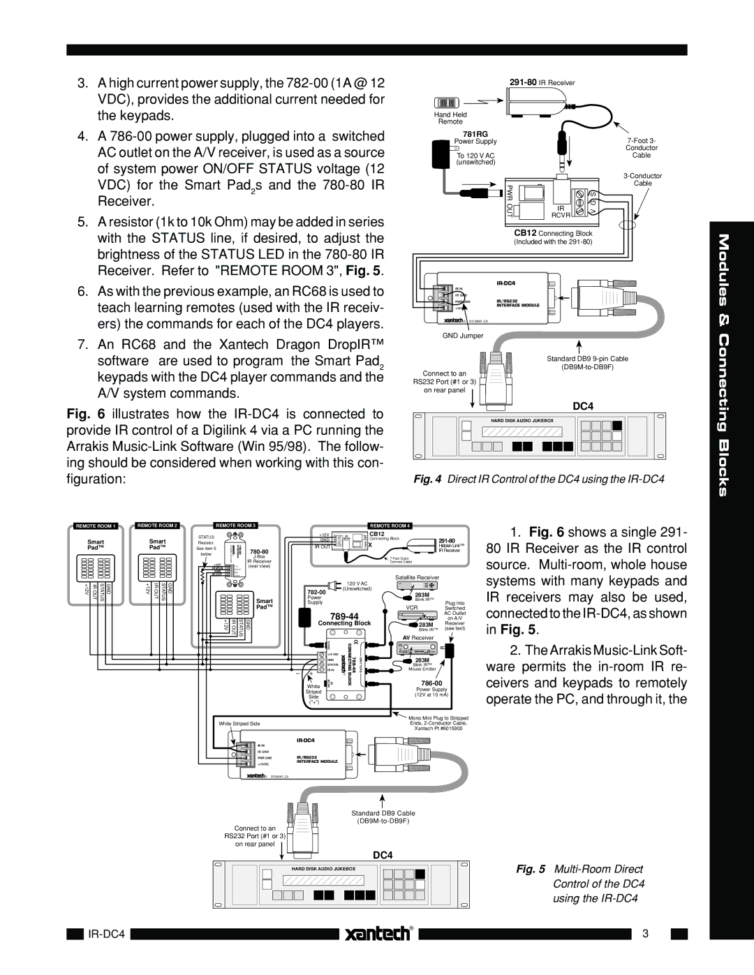
Fig. 6 illustrates how the IR-DC4 is connected to provide IR control of a Digilink 4 via a PC running the Arrakis Music-Link Software (Win 95/98). The follow- ing should be considered when working with this con- figuration:
| |
IR IN |
|
IR GND |
|
PWR GND | IR/RS232 |
+12VDC | INTERFACE MODULE |
| |
® SYLMAR, CA |
|
GND Jumper
Standard DB9
Connect to an RS232 Port (#1 or 3)
on rear panel
DC4
HARD DISK AUDIO JUKEBOX
Fig. 4 Direct IR Control of the DC4 using the IR-DC4
& Connecting Blocks
REMOTE ROOM 1
Smart
Pad™
+12V | IR OUT | GND STATUS |
|
|
|
|
|
|
REMOTE ROOM 2
Smart
Pad™
+12V | IR OUT | STATUS | GND |
|
|
|
|
|
|
|
|
|
|
|
|
REMOTE ROOM 3
STATUS
Resistor.
SYLMAR,CA91342 | ® | IRRECEIVER | IR Receiver | |
See item 5 |
|
|
| |
below |
|
|
| |
|
|
|
| |
+12V |
| +12V |
| (rear view) |
STATUS |
|
| ||
| STATUS |
| ||
GND |
| GND |
|
|
IR OUT |
| IR OUT |
| |
|
|
|
| Smart |
|
|
|
| Pad™ |
+12V | IR OUT | STATUS | GND | |
White Striped Side |
IR IN |
IR GND |
PWR GND |
+12VDC |
![]()
![]()
![]() ® SYLMAR, CA
® SYLMAR, CA
|
|
|
|
|
| REMOTE ROOM 4 |
| |
| +12V | V G | IR | OUT | CB12 |
|
| |
| GND | RCVR | Connecting Block | |||||
|
|
| PWR | X |
| |||
| IR OUT | S |
|
| Hidden Link™ | |||
|
|
|
|
|
|
|
| IR Receiver |
|
|
|
|
|
|
| 7 Foot Quick |
|
|
|
|
|
|
|
| Connect Cable |
|
|
|
|
|
|
|
| Satellite Receiver | |
|
|
|
| 120 V AC |
|
|
| |
|
|
| (Unswitched) |
|
| |||
|
|
|
|
|
| 283M |
| |
| Power |
|
|
|
|
|
| |
|
|
|
|
|
| Blink IR™ |
| |
| Supply |
|
|
|
|
| Plug into | |
|
|
|
|
|
| VCR | ||
|
|
|
|
|
|
| Switched | |
|
|
|
|
|
| AC Outlet | ||
|
|
|
|
| on A/V | |||
| Connecting Block | 283M | Receiver | |||||
|
|
|
|
|
|
| Blink IR™ | (see text) |
|
| 12VDC |
|
|
|
| AV Receiver |
|
|
|
| EMITTERS |
|
| |||
|
| IR RCVR |
|
| ||||
|
| +12 VDC |
|
|
|
|
| |
|
| GND |
|
|
| 283M |
| |
|
| STATUS |
|
|
| Blink IR™ |
| |
– | + | IR IN |
|
|
| Mouse Emitter |
| |
|
|
|
|
|
|
| ||
| White |
|
|
|
|
| Power Supply | |
| Striped |
|
|
|
|
| ||
|
|
|
|
|
| (12V at 10 mA) | ||
| Side |
|
|
|
|
| ||
| ("+") |
|
|
|
|
|
|
|
|
|
|
|
|
|
| Mono Mini Plug to Stripped | |
|
|
|
|
|
|
| Ends, | |
|
|
|
|
|
|
| Xantech Pt #6015900 | |
|
|
|
|
|
|
|
| |
IR/RS232 |
|
|
|
|
|
|
| |
INTERFACE MODULE |
|
|
|
|
| |||
1.Fig. 6 shows a single 291- 80 IR Receiver as the IR control source. Multi-room, whole house systems with many keypads and IR receivers may also be used, connected to the IR-DC4, as shown in Fig. 5.
2.The Arrakis
Standard DB9 Cable
![]()
![]()
![]() (DB9M-to-DB9F) Connect to an
(DB9M-to-DB9F) Connect to an ![]()
![]()
![]()
![]()
![]()
RS232 Port (#1 or 3)
on rear panel
DC4
HARD DISK AUDIO JUKEBOX
Fig. 5 Multi-Room Direct Control of the DC4 using the IR-DC4
3