LARGE SYSTEM APPLICATION
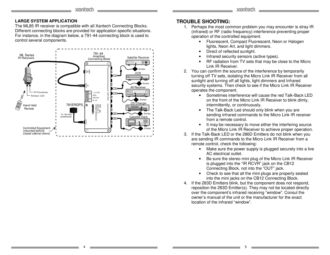
The ML85 IR receiver is compatible with all Xantech Connecting Blocks. Different connecting blocks are provided for application specific situations. For instance, in the diagram below, a
TROUBLE SHOOTING:
1. Perhaps the most common problem you may encounter is stray IR |
(infrared) or RF (radio frequency) interference preventing proper |
operation of the controlled equipment. |
∙ Fluorescent, Compact Fluorescent, Neon or Halogen |
lights, Neon Art, and light dimmers. |
∙ Direct of reflected sunlight. |
ML Series | ||
Amplified | ||
IR Receivers | ||
Connecting Block | ||
|
Satellite Receiver
∙ | Infrared security sensors (active types). |
∙ | RF radiation from TV sets that may be close to the Micro |
| Link IR Receiver. |
IR Photodiode
Talkback LED
OUT | HIGH IR |
RCVR | IR |
+ 12 V DC
G N D
S TATUS
I R I N
EMITTERS
Emitter
VCR
Emitter
AV Receiver
Emitter
2. You can confirm the source of the interference by temporarily |
turning off TV sets, isolating the Micro Link IR Receiver from all |
sunlight and turning off all lights, light dimmers and Infrared |
security systems. Then check to see if the Micro Link IR Receiver |
operates the component. |
∙ Sometimes interference will cause the red |
on the front of the Micro Link IR Receiver to blink dimly, |
Hand Held | 781ERGPS |
Remote |
|
| To 120 VAC |
| (unswitched) |
| 12 VDC |
Controlled Equipment (mounted behind closed cabinet doors)
® | CONNECTING | 791- 44 AMPLIFIE D |
| BLOCK |
|
CD Changer
Emitter
Cassette Deck
Emitter
intermittently, or continuously. |
∙ The |
sending infrared commands to the Micro Link IR receiver |
from a remote control. |
∙ It may be necessary to move either the interfering source |
of the Micro Link IR Receiver to achieve proper operation. |
3. If the |
are sending IR commands to the Micro Link IR Receiver from a |
remote control, check the following: |
∙ Make sure the power supply is plugged securely into a live |
AC electrical outlet. |
∙ Be sure the stereo mini plug of the Micro Link IR Receiver |
is plugged into the “IR RCVR” jack on the CB12 |
Connecting Block, not into the “OUT” jack. |
∙ Check to see that all the mini plugs are properly seated |
into the mini jacks on the CB12 Connecting Block. |
4. If the 283D Emitters blink, but the component does not respond, |
reposition the 283D Emitter(s). They may not be located directly |
over the component’s infrared receiving “window”. Consul the |
owner’s manual of the unit or the manufacturer for the exact |
location of the infrared “window”. |
4 |
|
|
| 5 |
|
|