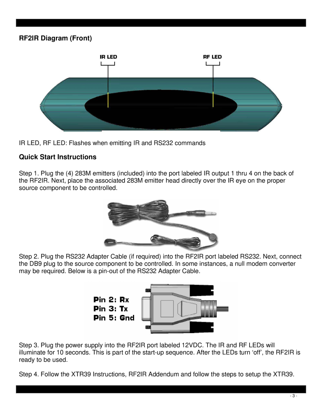
RF2IR Diagram (Front)
IR LED, RF LED: Flashes when emitting IR and RS232 commands
Quick Start Instructions
Step 1. Plug the (4) 283M emitters (included) into the port labeled IR output 1 thru 4 on the back of the RF2IR. Next, place the associated 283M emitter head directly over the IR eye on the proper source component to be controlled.
Step 2. Plug the RS232 Adapter Cable (if required) into the RF2IR port labeled RS232. Next, connect the DB9 plug to the source component to be controlled. In some instances, a null modem converter may be required. Below is a
Step 3. Plug the power supply into the RF2IR port labeled 12VDC. The IR and RF LEDs will illuminate for 10 seconds. This is part of the
Step 4. Follow the XTR39 Instructions, RF2IR Addendum and follow the steps to setup the XTR39.
- 3 -