8.0 DC Operation Option
Description
The DC Operation Option allows the user to power the 4071 from a DC voltage source in the
The user may easily switch between the AC Line supply and a DC source. This option is most useful for service and remote applications where AC power is not available.
A
Specifications:
∙Input Voltage Range:
∙Max. Power Consumption: 15 W
∙Switching Frequency: 200 KHz
∙Isolation Voltage: 500 VDC
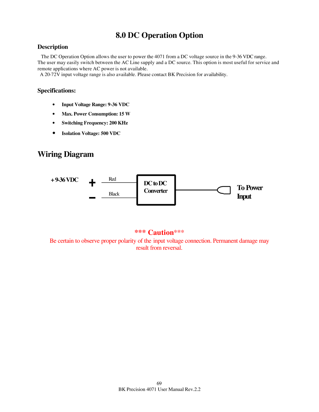
Wiring Diagram
+
Red | DC to DC |
|
|
| |
Black | Converter |
|
| ||
|
| |
|
|
|
|
|
|
*** Caution***
To Power Input
Be certain to observe proper polarity of the input voltage connection. Permanent damage may
result from reversal.
69
BK Precision 4071 User Manual Rev.2.2