5.23 External BPSK Mode
Introduction
The External BPSK mode generates a phase shift keyed signal of fixed amplitude. The logic level on the Ext FSK In connector is used as a modulating signal to shift the output phase between 0 and 180 degrees. The modulation is suppressed carrier; i.e. no carrier energy is present in the output waveform.
NOTE: External BPSK is implemented by sampling the Ext FSK In line at 1.43 MHz. When a change in the state of the line is detected, the output phase is switched. Since this input is sampled, there may be a small but unpredictable delay between when the input changes and when the output phase is switched. This delay is never greater than 1/1,430,000 sec (=700 nS). The net result is a 700 nS
the “other” modes menu.
External BPSK Mode Parameters
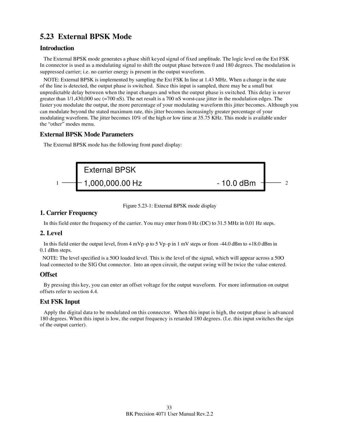
The External BPSK mode has the following front panel display:
1
External BPSK
1,000,000.00 Hz | - 10.0 dBm |
Figure 5.23-1: External BPSK mode display
2
1. Carrier Frequency
In this field enter the frequency of the carrier. You may enter from 0 Hz (DC) to 31.5 MHz in 0.01 Hz steps.
2. Level
In this field enter the output level, from 4 mVp
NOTE: The level specified is a 50O loaded level. This is the level of the signal, which will appear across a 50O load connected to the SIG Out connector. Into an open circuit, the output swing will be twice the value entered.
Offset
By pressing this key, you can enter an offset voltage for the output waveform. For more information on output offsets refer to section 4.4.
Ext FSK Input
Apply the digital data to be modulated on this connector. When this input is high, the output phase is advanced 180 degrees. When this input is low, the output frequency is retarded 180 degrees. (I.e. this input switches the sign of the output carrier).
33
BK Precision 4071 User Manual Rev.2.2