7.8.3 Digital Format
The Digital format was implemented as an easy way to design purely digital waveforms, i.e. waveforms that are either high or low. The digital format provides a very efficient way of representing waveforms that assume only a high or low value.
If the value of the data point is 0, then the SIG Out output is set to its minimum negative output voltage and the SYNC Out output is set to the logic Low state (0V) for that point.
If the value of the data point is
All rules for this format are identical to those for Floating Point Format, except that the Time or Point Number value need not be between +1.0 and
With this format, it is possible to specify each point of a digital waveform with only two bytes (a “1” or a “0” and a data separator character). This makes this format as efficient as binary format for data downloads. However since the data consists entirely of ASCII characters, it is easier to work with than binary format.
Example
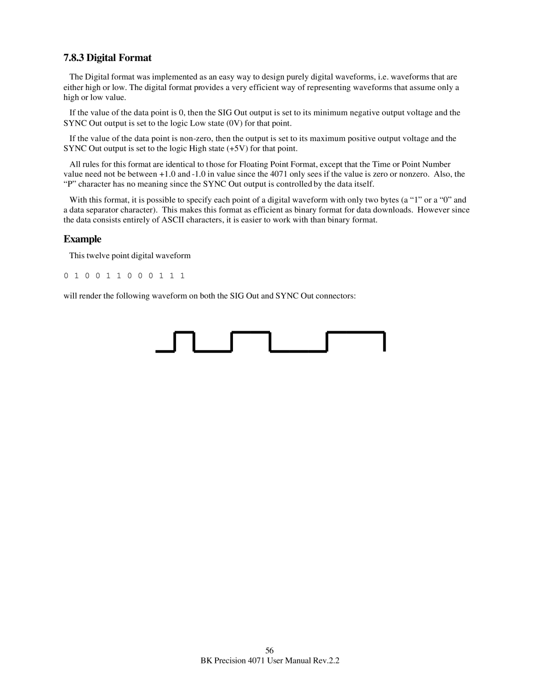
This twelve point digital waveform
0 1 0 0 1 1 0 0 0 1 1 1
will render the following waveform on both the SIG Out and SYNC Out connectors:
56
BK Precision 4071 User Manual Rev.2.2