5.18 Power & Voltage Measurement Mode
Introduction
The Power & Voltage Measurement mode measures the signal level on the Ext Mod In connector and displays the power and voltage level on the LCD display. The Power Measurement mode applies to frequencies in the DC to 50KHz range. An internal lowpass filter attenuates all signals outside this frequency range. The internal Digital Signal Processor (DSP) calculates a
To calculate power, "system impedance" must be specified. If the input signal were to be applied across a load resistor then that resistor would dissipate power. The power dissipated in the resistor is a function of the resistor's value. The value of this load resistor is referred to here as the "system impedance" which must be specified by the user. As opposed to instruments, which use a fixed value for this impedance (i.e. 50 or 600 O) the 4071 allows any value from 1 to 999 ohms to be used for power calculations.
The Ext Mod In jack is high impedance (about 30KO). If your system expects this signal to be terminated, place a resistor (of the appropriate terminating resistance) across this input.
Power & Voltage Measurement Mode Parameters
|
|
| Measured Level on mod input: |
|
| ||
|
|
| Volts: + 003 mV | Pwr res: | 600 ohm |
|
|
2 |
|
|
|
| |||
|
|
|
| ||||
|
|
|
|
|
|
|
|
|
|
|
|
|
|
|
|
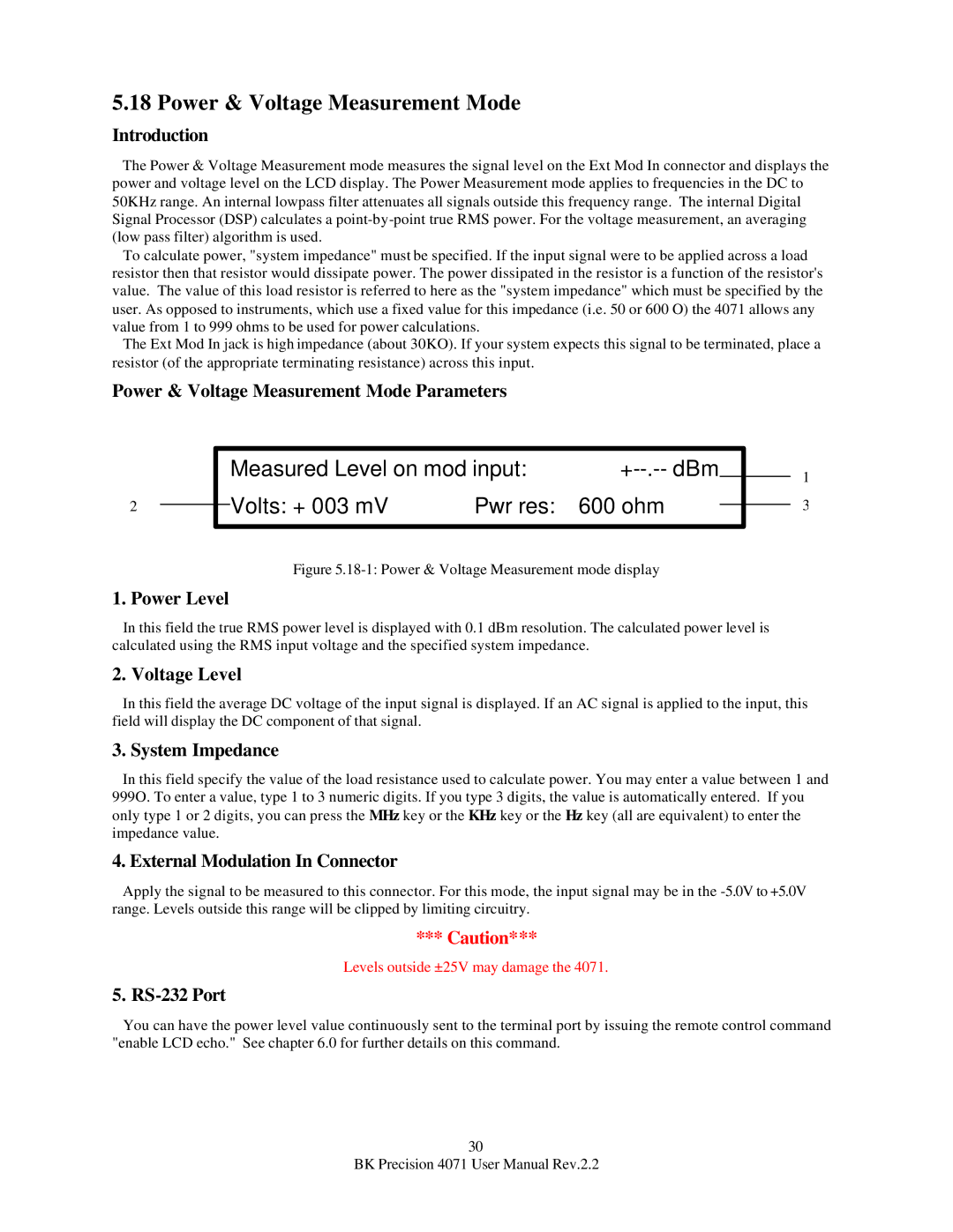
Figure 5.18-1: Power & Voltage Measurement mode display
1. Power Level
1
3
In this field the true RMS power level is displayed with 0.1 dBm resolution. The calculated power level is calculated using the RMS input voltage and the specified system impedance.
2. Voltage Level
In this field the average DC voltage of the input signal is displayed. If an AC signal is applied to the input, this field will display the DC component of that signal.
3. System Impedance
In this field specify the value of the load resistance used to calculate power. You may enter a value between 1 and 999O. To enter a value, type 1 to 3 numeric digits. If you type 3 digits, the value is automatically entered. If you only type 1 or 2 digits, you can press the MHz key or the KHz key or the Hz key (all are equivalent) to enter the impedance value.
4. External Modulation In Connector
Apply the signal to be measured to this connector. For this mode, the input signal may be in the
*** Caution***
Levels outside ±25V may damage the 4071.
5. RS-232 Port
You can have the power level value continuously sent to the terminal port by issuing the remote control command "enable LCD echo." See chapter 6.0 for further details on this command.
30
BK Precision 4071 User Manual Rev.2.2