User’s Manual
Model
Page
Model User’s Manual
B&K Precision
B+K Precision Corp
2.0 Installation and setup
1.0 Introduction
3.0 Operating controls and keys
4.0 Operating guide
Warranty information
6.0 Remote operation
7.0 Arbitrary waveform system
8.0 DC Operation Option
1 BK Precision 4071 User Manual Rev.2.2
1.0 Introduction
Figure 1.0-1:The BK Precision model
1.1 Description
1.2 Feature summary
Modes
2. SIG Out connector
2.0 Installation and setup
1. SYNC out connector
3. External Modulation In connector
4. External Trigger/Gating/FSK/BPSK input
result by exceeding this input voltage limit
8. Line in connector
6. External Arb Sync In / Out connector
7. RS232 Interface connector
3.0 Operating controls and keys
3.1 Mode key
3.2 Field arrow keys
3.3 Recall / Store key
3.7 é, ê, è, ç keys
3.5 Trigger key
3.6 Numeric keys 0 to 9, - and
3.10 One Touch Mode Keys
3.8 Clear key
3.9 MHz/dBm, KHz/Vp-p/Sec, Hz/mVp-p/mSkeys
4.0 Operating guide
4.1 Changing frequency
4.2 Changing level
4.3 Changing operating modes
4.5.2Entering a new value
4.5 Changing values
4.5.1 Modifying an existing value
5.0 Mode descriptions
5.1 Basic Sinewave CW Mode
Sinewave Mode
1,000,000.00 Hz
5.2 Internal AM Mode
Int AM: 1,000 Hz
Percent Mod: 100%
PEP level: -10.0dBm
5.3 External AM Mode
External AM
Input gain:
External AM Mode Parameters
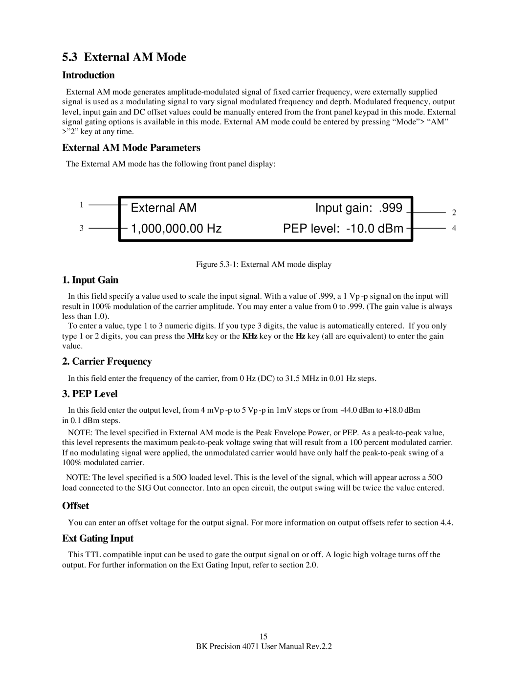
5.4 Internal FM Mode
Int FM: 1,000 Hz
Pk dev: 10,000 Hz
Internal FM Mode Parameters
5.5 External FM Mode
External FM
External FM Mode Parameters
1. Peak Frequency Deviation
2. Peak Phase Deviation
5.6 Internal PM Mode
Int PM: 1,000 Hz
Pk dev: 180 deg
1. Peak Phase Deviation
5.7 External PM Mode
External PM
External PM Mode Parameters
5.8 Sweep Mode
St: 1,000,000.00 Hz
Stp: 20,000,000.00 Hz
Linear | Cont | Up | Time: 60,000 mS -10.0dBm
SYNC Out Connector
5. Up / Down sweep
6. Sweep time
7. Level
5.9 Internal FSK Mode
Int FSK: 1,000 Hz
Mark: 1,000,000.00 Hz
Space: 2,000,000.00 Hz
5.10 External FSK Mode
Ext FSK
External FSK Mode Parameters
1. Mark Frequency
5.11Burst Mode Introduction
Burst Mode
Trig
10,000 mS
5.12 Internal SSB Mode
Int SSB: 1,000 Hz
Upper Sideband
Internal SSB Mode Parameters
5.13 External SSB Mode
External SSB
External SSB Mode Parameters
1. Upper/Lower Sideband selections
5.16 DTMF Generation Mode
DTMF generation: #
Duration: 200 mS
Delay
2. DTMF Duration
3. DTMF Delay
4. Level
Offset
5.17 DTMF Detection Mode
DTMF detection on Ext Mod input 1 2 3 # A
DTMF Detection Mode Parameters
1. DTMF detected digits
5.18 Power & Voltage Measurement Mode
Power & Voltage Measurement Mode Parameters
1. Power Level
4. External Modulation In Connector
5.19 Arbitrary Mode
5.20 Remote Mode
RS-232baud rate:
Use 0-9,arrow keys, or knob to select
5.22 Internal BPSK Mode
1Int BPSK: 1,000 Hz
10.0 dBm
Internal BPSK Mode Parameters
5.23 External BPSK Mode
External BPSK
External BPSK Mode Parameters
1. Carrier Frequency
3. Phase Offset
5.24 Dualtone Generation Mode
10,000 Hz F2
5,000 Hz
Dualtone Examples
Ext Gating Input
Using the Data Modulation Mode
5.25 Data Modulation Mode
Data
Data Modulation Mode Parameters
Downloading Modulation Message Data
Example Message
Offset
Ext Trigger Input
Triggering the Transmission
Saving the Message
5.26 Voltage Controlled Oscillator VCO Mode
Start
0 Hz
End: 1,000,000.00 Hz
6.2 Connecting
6.0 Remote Operation
6.1 Introduction
6.3 Checking your connection with Hyper Terminal
6.4 Remote Control Operation
6.5 Remote Control Programming Rules
6.6 Remote Control Commands
Z Y X C
E1,0 - Enable, Disable LCD echo to terminal
V - Report hardware and software versions
Stp: 31,500,000.00 Hz
Linear | Trig | Up | Time: 10,000 mS
10.0dBm
0 Hz
6.7 Remote Control Examples
Example
Example
Example
7.0Arbitrary Waveform Mode
7.1Quick Start Guide
9 pin - 9-pincable
9 pin - 25 pin cable adapter
7.2 Introduction to the Arbitrary Waveform System
Introduction
7.3 Switching Modes
7.2.2 Feature Summary
Function Generator
Pulse Generator
Phase: 126.35 deg
2. Phase
7.4 Arbitrary Waveform Mode
Arb Mode Int
7.5 Function Generator Mode
Function Gen
Wave: Pos Ramp
Cont Rep Freq: 100,000 Hz
7.6 Pulse Generator Mode
Pulse Gen
Only? N Duty Cycle: 50 %
Cont Rep Freq: 2,000,000.00 Hz
7.7.1 Using WAVELOAD.EXE
7.7 Downloading arbitrary waveforms
Saving Arbitrary Waveforms
C:>WAVELOAD /COMx /y /baud:z filename.ext
7.7.2 Using your own program
7.8 Data Formats
7.8.1 Floating Point Format
Example
Rules for Floating Point format
Example
7.8.2 Time & Value Floating Point Format
Example #2
7.8.3 Digital Format
Example
Rules for Integer format
7.8.4 Integer Format
Example
Example
7.8.5 Hexadecimal Format
Rules for Hexadecimal format
Example
7.8.6 Binary Format
Rules for Binary format
7.9 Multiple Units Locking
Generator
7.9.1 Introduction to Multiple Arb Locking
Quick Start Guide
More on Phase Offsets
Phase Resolution
Waveform Size Restrictions
Example
Program Listing - ARB.BAS
7.10 Example Arb Program
ARB.BAS
63 BK Precision 4071 User Manual Rev.2.2
F = Floating Point I = Integer
PRINT #1, PointVal
Send Floating point number to
RETURN
Send Integer data to
PRINT #1, a
Send integer value to
RETURN
66 BK Precision 4071 User Manual Rev.2.2
67 BK Precision 4071 User Manual Rev.2.2
68 BK Precision 4071 User Manual Rev.2.2
Wiring Diagram
Specifications
8.0 DC Operation Option
Description
70 BK Precision 4071 User Manual Rev.2.2
9.0 4071 Specifications
Operating Modes
UPDATE
10.0 Software CD
CALIBRATE
REMOTE
will cause permanent damage to the
Hardware Setup
Appendix A
73 BK Precision 4071 User Manual Rev.2.2
74 BK Precision 4071 User Manual Rev.2.2
75 BK Precision 4071 User Manual Rev.2.2
76 BK Precision 4071 User Manual Rev.2.2
Television Remote Control Example
Appendix B
Hardware Setup
Background
78 BK Precision 4071 User Manual Rev.2.2
79 BK Precision 4071 User Manual Rev.2.2
80 BK Precision 4071 User Manual Rev.2.2
Date Purchased: __________
Limited Two-YearWarranty
Model Number: ______________
Service Information
82 BK Precision 4071 User Manual Rev.2.2
2002 B&K Precision Corp
22820 Savi Ranch Pkwy Yorba Linda, CA 92887 USA
PN: 481-419-9-001Printed in the U.S.A