3. External Modulation In connector
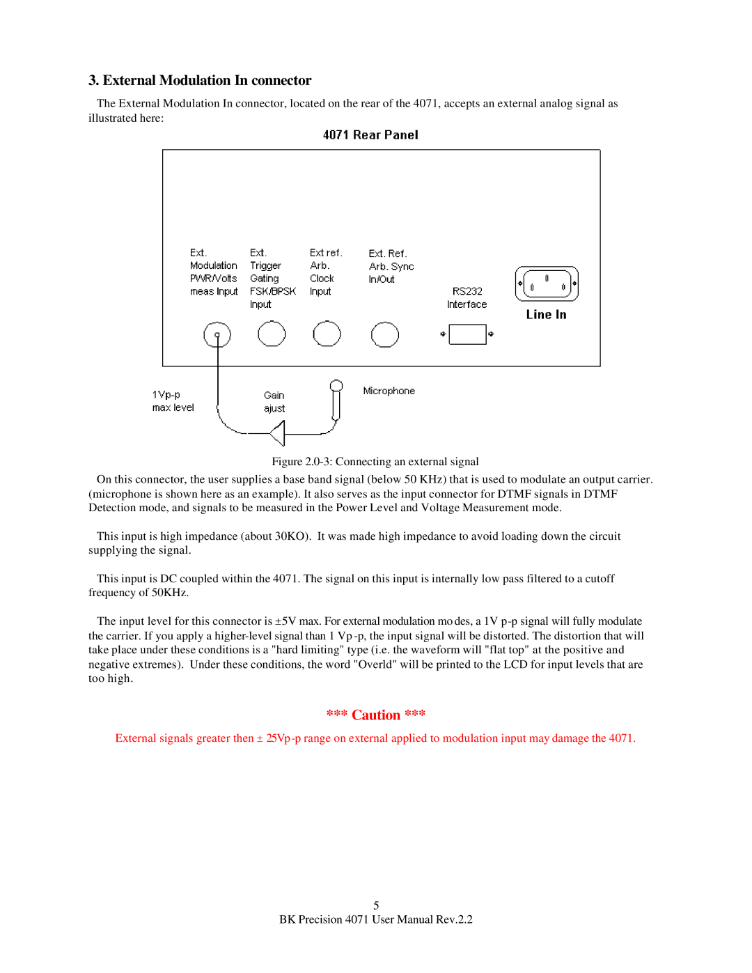
The External Modulation In connector, located on the rear of the 4071, accepts an external analog signal as illustrated here:
Figure 2.0-3: Connecting an external signal
On this connector, the user supplies a base band signal (below 50 KHz) that is used to modulate an output carrier. (microphone is shown here as an example). It also serves as the input connector for DTMF signals in DTMF Detection mode, and signals to be measured in the Power Level and Voltage Measurement mode.
This input is high impedance (about 30KO). It was made high impedance to avoid loading down the circuit supplying the signal.
This input is DC coupled within the 4071. The signal on this input is internally low pass filtered to a cutoff frequency of 50KHz.
The input level for this connector is ±5V max. For external modulation mo des, a 1V p-p signal will fully modulate the carrier. If you apply a higher-level signal than 1 Vp -p, the input signal will be distorted. The distortion that will take place under these conditions is a "hard limiting" type (i.e. the waveform will "flat top" at the positive and negative extremes). Under these conditions, the word "Overld" will be printed to the LCD for input levels that are too high.
*** Caution ***
External signals greater then ±
5
BK Precision 4071 User Manual Rev.2.2